
Crossed cylindrical roller guide rail for instrument lathe

A cylindrical roller and instrument lathe technology, applied in the field of machine tools, can solve the problems of poor follow-up performance, difficult to guarantee the working accuracy of machine tools, and short service life.

Inactive Publication Date: 2011-10-05
罗邦林
View PDF2 Cites 1 Cited by
  • Summary
  • Abstract
  • Description
  • Claims
  • Application Information

AI Technical Summary

Problems solved by technology

[0002] The cross carriage and the upper carriage are installed on the instrument lathe. There is a horizontal sliding guide rail between the cross carriage and the lathe bed, and there is a longitudinal sliding guide rail between the upper carriage and the cross carriage. The tool is installed on the upper carriage. The existing lathe The structure of each guide rail is composed of a slide plate and a chute, and the reciprocating motion is performed by surface contact. The disadvantages of the surface contact sliding guide rail are large friction resistance, especially large starting friction, poor follow-up performance, low stability, and wear resistance. Poor performance, short service life, difficult to guarantee the working accuracy of the machine tool

Method used


Image

  • Crossed cylindrical roller guide rail for instrument lathe
  • Crossed cylindrical roller guide rail for instrument lathe
  • Crossed cylindrical roller guide rail for instrument lathe

Examples


Embodiment Construction

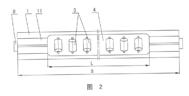
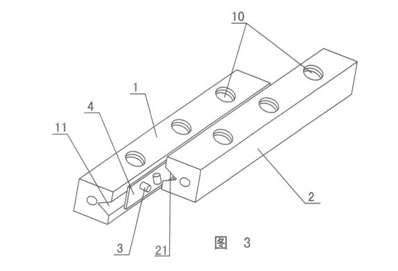
[0011] The invention relates to a crossed cylindrical roller guide rail of an instrument lathe, such as figure 1 — Figure 4 As shown, it includes a lathe bed, a cross carriage and an upper carriage, and is characterized in that a cylindrical roller guide rail pair is installed between the lathe bed and the cross carriage and between the cross carriage and the upper carriage, and the cylindrical roller The sub guide rail pair includes two guide rails 1 and 2 with V-shaped raceways 11 and 21. Cylindrical rollers 3 are installed in the V-shaped raceways 11 and 21. The cylindrical rollers 3 have cages 4, and the adjacent ones have cages The cylindrical rollers 3 of the frame are arranged in a 90° cross arrangement with each other in the V-shaped raceways 11 and 21 . The most substantive technology of this program is to install the cylindrical rollers 3 in the two guide rails 1, 2 of the V-shaped raceways 11, 21, especially the adjacent cylindrical rollers 3 in the V-shaped racew...


PUM


Abstract

The invention discloses a crossed cylindrical roller guide rail for an instrument lathe, which comprises a lathe body, a cross support plate and an upper support plate. The crossed cylindrical roller guide rail is characterized in that a cylindrical roller guide rail pair is arranged between the lathe body and the cross support plate as well as between the cross support plate and the upper support plate; the cylindrical roller guide rail pair comprises two guide rails provided with V-shaped raceways; cylindrical rollers are arranged in the V-shaped raceways and are provided with retainers; and adjacent cylindrical rollers provided with the retainers are arrayed in the V-shaped raceways at an angle of 90 degrees in a crossed way. The scheme has the benefits of small cylindrical rolling friction resistance, particularly small starting friction force, favorable following performance, favorable operation stability, small elastic deformation, more effective motion bodies, little abrasion and long service life; the adjacent cylindrical rollers (alternative) are arrayed in the V-shaped raceways in the crossed way and are mutually staggered at the angle of 90 degrees; the cylindrical rollers can bear loads in each direction; the sliding clearance between the guide rails is eliminated; and the contacted area of the cylindrical rollers is large.

Description

technical field [0001] The invention relates to a lathe, in particular to a crossed cylindrical roller guide rail for an instrument lathe, and belongs to the field of machine tools. Background technique [0002] The cross carriage and the upper carriage are installed on the instrument lathe. There is a horizontal sliding guide rail between the cross carriage and the lathe bed, and there is a longitudinal sliding guide rail between the upper carriage and the cross carriage. The tool is installed on the upper carriage. The existing lathe The structure of each guide rail is composed of a slide plate and a chute, and the reciprocating motion is performed by surface contact. The disadvantages of the surface contact sliding guide rail are large friction resistance, especially large starting friction, poor follow-up performance, low stability, and wear resistance. The performance is poor, the service life is short, and the working accuracy of the machine tool is difficult to guaran...

Claims


Application Information

Patent Timeline
IPC IPC(8): B23Q1/01
Inventor 罗邦林
Owner 罗邦林
Learn More