Method for die-forging forging piece by adopting single-arm hoisting ring for petroleum drilling
A processing method and oil drilling technology, which is applied in the processing field of single-arm lifting ring die forging forgings for oil drilling, can solve the problems of low qualified rate of finished products, unreasonable process, complex supporting facilities, etc., and achieve good surface quality and mechanical performance indicators Excellent effect
- Summary
- Abstract
- Description
- Claims
- Application Information
AI Technical Summary
Problems solved by technology
Method used
Image
Examples
Embodiment 1
[0038] Name: DH150 lifting ring, drawing number EG101501-01, production sequence number QA10001
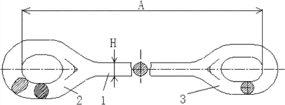
[0039] Step 1. To elongate the stem part 1 of the single-arm ring die forging, in order to ensure the pairing of the rings, the rod part 1 cannot be pulled out to the size at one time, and the rod part 1 should be roughly dropped first. Rod part 1 fell to 5mm larger than the survival size, and the diameter and length of the rod were controlled.
[0040] Step 2, then use the mold to round the big end 2 and the small end 3 of the single-arm suspension ring;
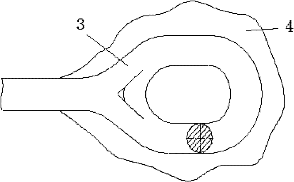
[0041] Step 3. Then flatten the big end 2 and small end 3 of the single-arm lifting ring, and punch special-shaped holes; (according to the shape of the inner hole of the lifting ring, configure the corresponding punch. figure 1 ring inner hole diagram)
[0042] Step 4, die forging the big end 2 and small end 3 of the single-arm suspension ring;
[0043] Step 5. Cut off the flash 4 on the big end 2 and the small end 3 of the...
Embodiment 2
[0052] Name: DH250 lifting ring, drawing number EG105001-01, production sequence number QA9001
[0053]Step 1. To elongate the stem part 1 of the single-arm ring die forging, in order to ensure the pairing of the rings, the rod part 1 cannot be pulled out to the size at one time, and the rod part 1 should be roughly dropped first. Rod part 1 falls to 5mm-10mm larger than the survival size, and the diameter and length of the rod are controlled. The tolerance range of the rod part 1 is 8mm, and the tolerance of each pair is less than 3mm.
[0054] Step 2, then use the mold to round the big end 2 and the small end 3 of the single-arm suspension ring;
[0055] Step 3. Then flatten the big end 2 and small end 3 of the single-arm lifting ring, and punch special-shaped holes; (according to the shape of the inner hole of the lifting ring, configure the corresponding punch. figure 1 ring inner hole diagram)
[0056] Step 4, die forging the big end 2 and small end 3 of the single-arm...
Embodiment 3
[0066] Name: DH750 lifting ring, drawing number EG175002
[0067] Step 1. To elongate the stem part 1 of the single-arm ring die forging, in order to ensure the pairing of the rings, the rod part 1 cannot be pulled out to the size at one time, and the rod part 1 should be roughly dropped first. Rod part 1 falls to 5mm-10mm larger than the survival size, and the diameter and length of the rod are controlled. The tolerance range of the rod part 1 is 10mm, and the purpose is to use the tolerance range of the rod part 1 to control the length. Because the material used for the rod part 1 is certain, the tolerance of the rod part 1 moves up when the rod part 1 is long; the tolerance of the rod part 1 moves down when the rod part 1 is short, of course, the size must be within the tolerance range. Because the lifting rings are used in pairs, the tolerance of each pair is less than 3mm.
[0068] Step 2, then use the mold to round the big end 2 and the small end 3 of the single-arm su...
PUM
 Abstract
Description
Claims
Application Information
 - R&D
- Intellectual Property
- Life Sciences
- Materials
- Tech Scout
- Unparalleled Data Quality
- Higher Quality Content
- 60% Fewer Hallucinations
Browse by: Latest US Patents, China's latest patents, Technical Efficacy Thesaurus, Application Domain, Technology Topic, Popular Technical Reports.
© 2025 PatSnap. All rights reserved.Legal|Privacy policy|Modern Slavery Act Transparency Statement|Sitemap|About US| Contact US: help@patsnap.com


