Blower and heat pump utilizing said blower
A technology of heat pump device and blower, which is applied to household heating, components of pumping device for elastic fluid, machine/engine, etc., can solve problems such as airflow turbulence, achieve airflow fluctuation suppression, increase overlap height, sharp Variation reduction effect
- Summary
- Abstract
- Description
- Claims
- Application Information
AI Technical Summary
Problems solved by technology
Method used
Image

Examples
Embodiment approach 1
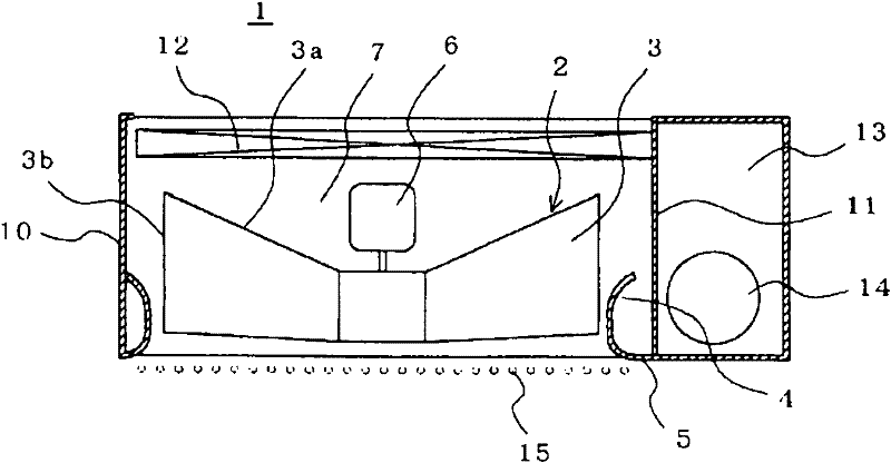
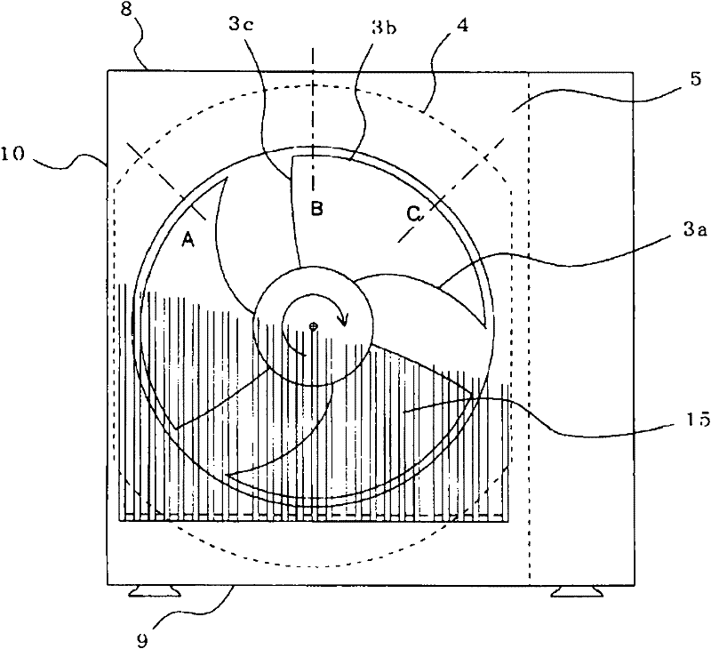
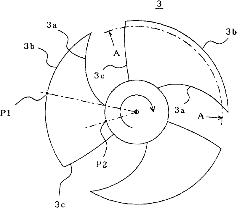
[0031] figure 1 It is a horizontal sectional view showing the outdoor unit of the air conditioner according to Embodiment 1 of the present invention, figure 2 It is a front view showing the outdoor unit of the air conditioner of Embodiment 1, image 3 It is a front view showing the propeller fan mounted in the outdoor unit of the air conditioner according to Embodiment 1, Figure 4 It is a cylindrical cross-sectional development view showing the propeller fan mounted in the outdoor unit of the air conditioner according to Embodiment 1, Figure 5 yes means figure 2 A sectional view of the shape of the bell mouth in Part A, Figure 6 yes means figure 2 A sectional view of the flare shape in Part B, Figure 7 It is another front view which shows the outdoor unit of the air conditioner of Embodiment 1, Figure 8 It is a supplementary cross-sectional view illustrating the characteristics of the bell of the outdoor unit of the air conditioner according to Embodiment 1, Fi...
Embodiment approach 2
[0083] Figure 10 It is a horizontal sectional view showing the outdoor unit of the air conditioner according to Embodiment 2 of the present invention, Figure 11 It is a front view showing the outdoor unit of the air conditioner according to Embodiment 2, omitting the protection grille.
[0084] In the above-mentioned first embodiment, when viewed from the front of the propeller fan 3, the side opposite to the machine room 13 is the horizontal plate 10. In this second embodiment, the side opposite to the machine room 13 is the heat exchanger 12. Like Embodiment 1, the surface facing the blowing plate 5 is covered with the heat exchanger 12 .
[0085] When the degree of negative pressure near the propeller fan 3 is strong and there is a heat exchanger 12 as a resister, the velocity of the gas flowing into the propeller fan 3 changes according to its distance from the propeller fan 3, as described above The resister allows gas to pass close to the radially outer side of prope...
Embodiment approach 3
[0092] Figure 13 It is a horizontal sectional view of the outdoor unit of the heat pump water heater according to Embodiment 3, Figure 14 It is a front view of the outdoor unit of the heat pump water heater according to Embodiment 3, omitting the protective grille.
[0093] The third embodiment is the same as the second embodiment, the opposite side of the machine room 13 is the heat exchanger 12, and the surface opposite to the blowing plate 5 is covered by the heat exchanger 12, and the lower part of the outdoor unit 1 is provided with a cooling system. Water heat exchanger 17 for heat exchange between agent and water.
[0094] The water heat exchanger 17 occupies the lower part of the outdoor unit 1 , and the upper surface 17 a of the air passage chamber becomes one surface of the plate constituting the air passage chamber 7 as viewed from the propeller fan 3 .
[0095] That is, in the cross section of the air passage chamber 7, the lengths of the heat exchanger 12 and ...
PUM
 Abstract
Description
Claims
Application Information
 - R&D
- Intellectual Property
- Life Sciences
- Materials
- Tech Scout
- Unparalleled Data Quality
- Higher Quality Content
- 60% Fewer Hallucinations
Browse by: Latest US Patents, China's latest patents, Technical Efficacy Thesaurus, Application Domain, Technology Topic, Popular Technical Reports.
© 2025 PatSnap. All rights reserved.Legal|Privacy policy|Modern Slavery Act Transparency Statement|Sitemap|About US| Contact US: help@patsnap.com