Function test platform and method for transformer relaying protection device based on real time digital system (RTDS)
A relay protection device, transformer technology, applied in the field of simulation
- Summary
- Abstract
- Description
- Claims
- Application Information
AI Technical Summary
Problems solved by technology
Method used
Image
Examples
example 1
[0043] Example 1, transformer air-drop test:
[0044] 1) The high-voltage side of the three-winding transformer sub-model 1 is air-dropped 10 times, and at least two of the three-phase peak inrush currents should be greater than 2 times the rated current peak value.
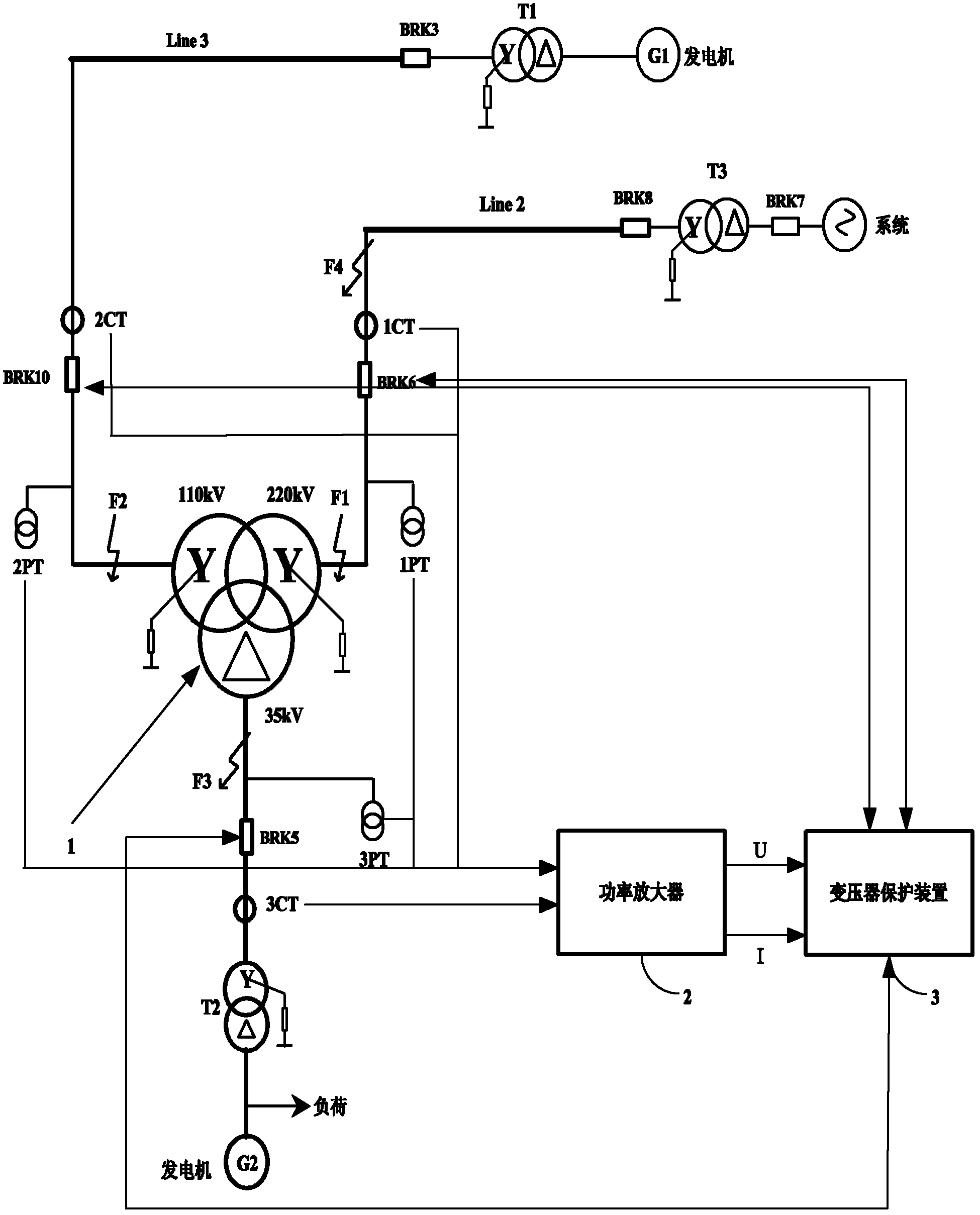
[0045] At this time, 10 airdrop tests are recorded in the corresponding logical operation file, and the logical operation object is the high-voltage side of the three-winding transformer sub-model 1. The logical operation corresponding to each airdrop test is airdrop, and the corresponding fault state configuration parameter is the peak value of the inrush current , and in at least two or three airdrop tests, the peak value of the inrush current is greater than 2 times the peak value of the rated current.
[0046] 2) Airdrop 10 times from the medium voltage side, at least twice of which the maximum inrush current peak value in the three phases should be greater than 2 times the rated current peak value.
[0047]...
example 2
[0050] Example 2, metal faults inside and outside the differential protection zone
[0051] 1) Under the condition of full load or no load of the transformer, simulate the following metal faults in the differential protection zone:
[0052] ①. Single-phase grounding inside the transformer;
[0053] The internal single-phase grounding of the transformer refers to the connection between the winding and the casing. At this time, the logical operation object is the winding and the casing, and the corresponding fault state configuration parameters are full load (no load) and single-phase grounding.
[0054] ② One or a combination of single-phase ground faults, two-phase ground faults, two-phase short circuits, three-phase short circuits, and three-phase short-circuit ground faults occur on the high-voltage side F1 and / or medium-voltage side F2;
[0055] At this time, the logical operation object is the high-voltage side fault point F1 and / or the medium-voltage side F2 of the three...
example 3
[0061] Example 3, conversion failure:
[0062] Under the condition of transformer full load, the transition of different fault types at the same point outside the F4 area of the high voltage side fault point is simulated. Fault type: Single-phase ground fault is converted to two-phase ground fault, AN→ABN, BN→BCN, CN→CAN, and the fault conversion time is 20~300ms.
[0063] Taking AN→ABN as an example, its logical operation object is the fault point F4 in the high-voltage side zone of the three-winding transformer sub-model 1: its logical operation and corresponding fault state configuration parameters include:
[0064] fully loaded;
[0065] AN: 20-300ms;
[0066] conversion;
[0067] ABN.
[0068] Among them, AN, ABN and 20-300ms are fault state configuration parameters.
PUM
 Abstract
Description
Claims
Application Information
 - R&D
- Intellectual Property
- Life Sciences
- Materials
- Tech Scout
- Unparalleled Data Quality
- Higher Quality Content
- 60% Fewer Hallucinations
Browse by: Latest US Patents, China's latest patents, Technical Efficacy Thesaurus, Application Domain, Technology Topic, Popular Technical Reports.
© 2025 PatSnap. All rights reserved.Legal|Privacy policy|Modern Slavery Act Transparency Statement|Sitemap|About US| Contact US: help@patsnap.com


