Bidirectional spring brake and electric equipment

A two-way spring, electrical equipment technology, applied in the field of brakes, can solve the problems of complex structure, inflexible use, small braking torque, etc. of the brake, and achieve the effects of simple structure, flexible use and high reliability

Active Publication Date: 2013-07-03
捷和电机(江西)有限公司
View PDF0 Cites 0 Cited by
  • Summary
  • Abstract
  • Description
  • Claims
  • Application Information

AI Technical Summary

Problems solved by technology

[0003] The object of the present invention is to provide a spring brake, aiming at solving the problems of the existing brakes such as complex structure, small braking torque, poor reliability, inflexible use, high cost and can only be applied to the input device end

Method used


Image

  • Bidirectional spring brake and electric equipment
  • Bidirectional spring brake and electric equipment
  • Bidirectional spring brake and electric equipment

Examples


Embodiment Construction

[0016] In order to make the object, technical solution and advantages of the present invention clearer, the present invention will be further described in detail below in conjunction with the accompanying drawings and embodiments. It should be understood that the specific embodiments described here are only used to explain the present invention, not to limit the present invention.

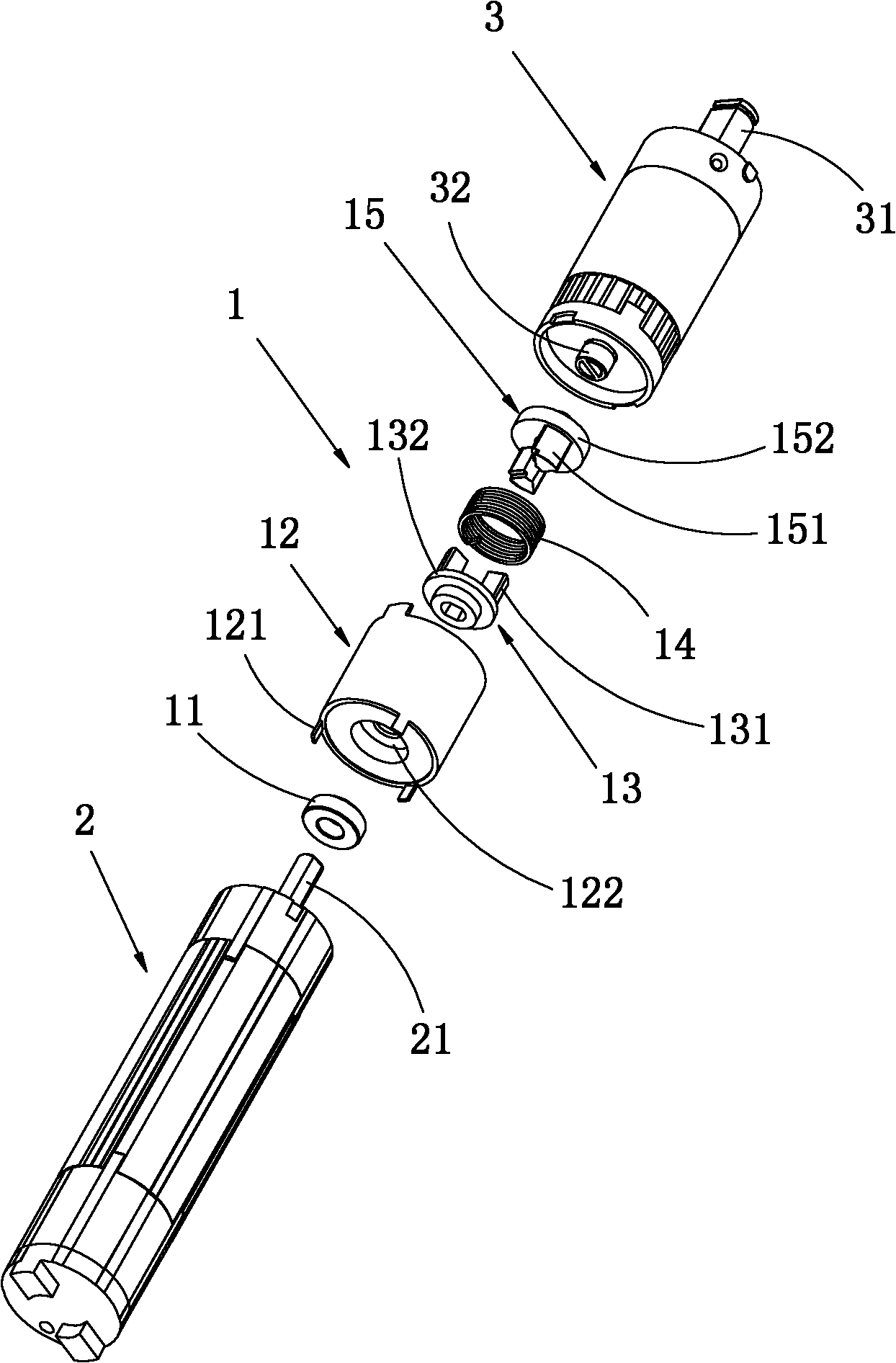
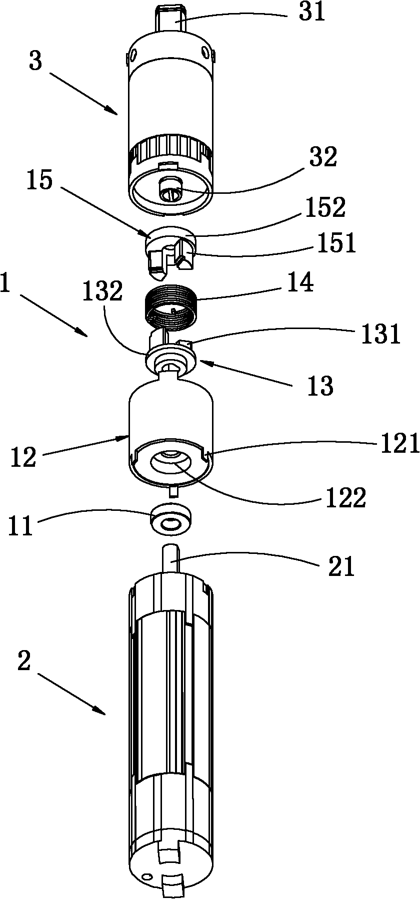
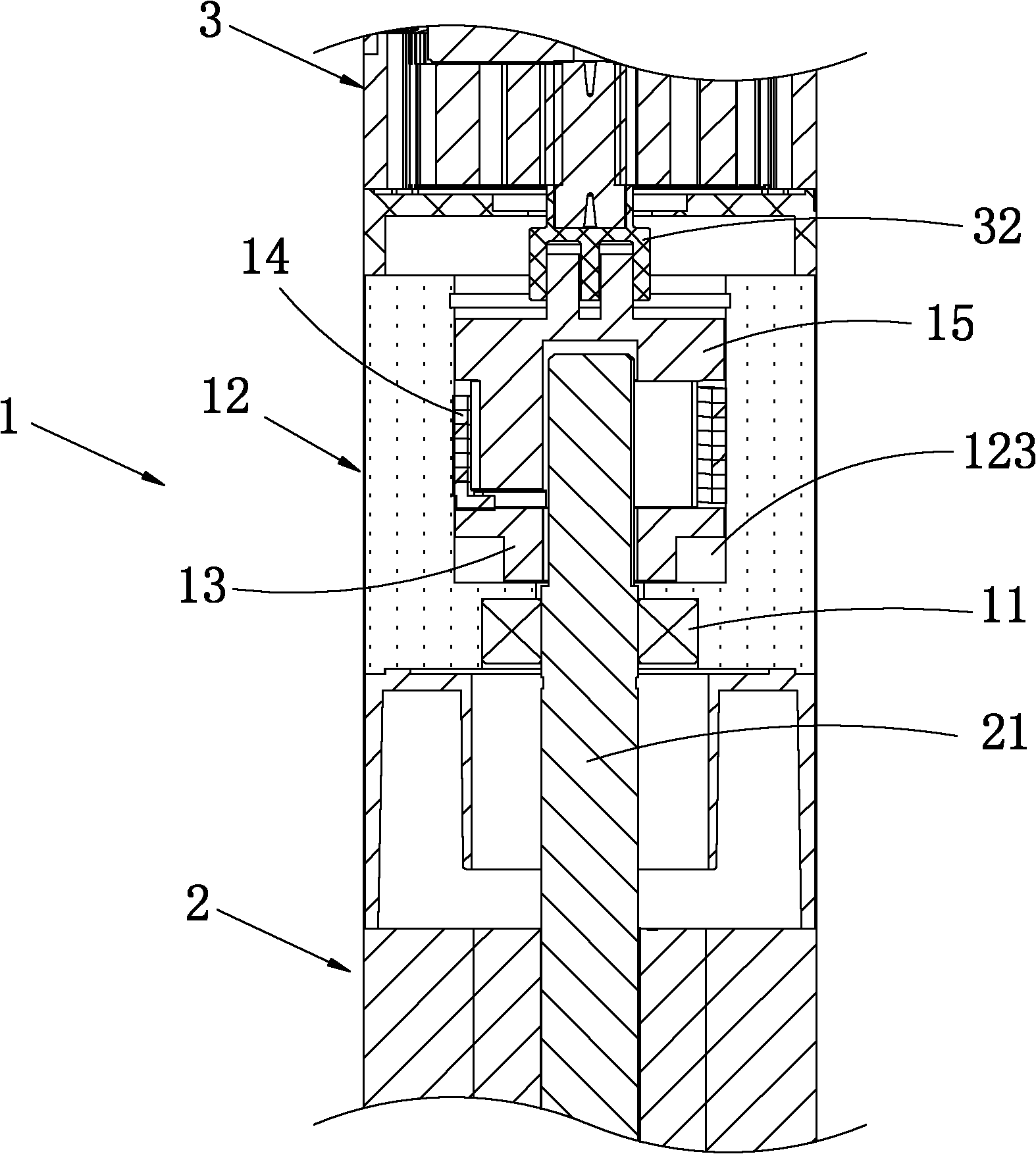
[0017] The invention provides a two-way spring brake, which comprises a brake sleeve with an accommodating cavity inside, an input spring finger for connecting with a first input shaft of an external input device, and an input spring claw for connecting with a second input shaft of an external output device. The output spring claw and the springs that can be engaged with the input spring claw and the output spring claw respectively, the input spring claw, the spring and the output spring claw are sequentially placed in the accommodating cavity.

[0018] In the present invention, the two-way spring ...


PUM


Abstract

The invention relates to the technical field of brakes and discloses a bidirectional spring brake. The bidirectional spring brake comprises a brake cover with an inner accommodating cavity, an input spring pusher dog which is connected with a first input shaft of an external input device, an output spring pusher dog which is connected with a second input shaft of the external input device and springs which can be respectively clamped on the input spring pusher dog and the output spring pusher dog. The input spring pusher dog, the spring and the output spring pusher dog are sequentially arranged in the accommodating cavity. The bidirectional spring brake disclosed by the invention is a mechanism and can be used at an input device end and an output device end. The invention has the advantages of low cost, simple structure, high reliability and flexibility in use. The torsion is large during brake, and a brake function can be accurately realized in time. The torsion strength can be adjusted by the springs according to actual conditions. The invention further provides electric equipment comprising the bidirectional spring brake.

Description

technical field [0001] The invention relates to the technical field of brakes, in particular to a two-way spring brake and electrical equipment including the two-way spring brake. Background technique [0002] In the prior art, brakes are generally provided between the input device and the output device in some electrical equipment, and the brake can ensure that the electrical equipment has the functions of self-locking, accurate positioning and high safety factor, such as cranes, roller shutters, etc. and other electrical equipment to prevent accidents caused by sudden power failure or power loss of the input device. If there is no electricity or no power, the roller blind machine will slide down due to its own weight, causing a safety accident, and the roller blind machine cannot be positioned accurately, so the brake has been widely used in the existing electrical equipment, but the brake in the prior art The brake device absorbs the brake components through the electrom...

Claims


Application Information

Patent Timeline
Patent Type & Authority Patents(China)
IPC IPC(8): F16D59/00
Inventor 俞从高谭长发石巍
Owner 捷和电机(江西)有限公司
Why Eureka
Try Eureka