
Artificial blood vessel for realizing zero-angle bypass grafting

An artificial blood vessel, zero-angle technology, applied in the field of artificial blood vessels, can solve the problems of intimal hyperplasia, difficulty in performing surgery, and unclear mechanism of intimal hyperplasia, so as to prevent terminal restenosis, facilitate operation, and improve hemodynamics The effect of the learning environment

Inactive Publication Date: 2011-09-28
BEIHANG UNIV
View PDF6 Cites 3 Cited by
  • Summary
  • Abstract
  • Description
  • Claims
  • Application Information

AI Technical Summary

Problems solved by technology

However, the mechanism of vascular intimal hyperplasia corresponding to the bottom surface of the anastomosis at the main artery that leads to the failure in the later stage of the operation is still unclear.
But regardless of the mechanism, it is an indisputable fact that the blood flow will be disturbed after bypass surgery to generate vortices at the bottom of the downstream suture, and this vortex is the root cause of intimal hyperplasia
[0003] The study found that in traditional vascular bypass surgery, the angle between the main vessel and the bypass vessel is generally between 60 degrees and 30 degrees, and the smaller the bypass angle, the more difficult the operation is, and the larger the bypass angle is, the more difficult the operation will be. easy
However, studies have shown that the greater the bridge angle, the greater the disturbance of the blood flow after the bridge, and the greater the vortex generated at the downstream suture, which is more likely to cause intimal hyperplasia on the bottom surface of the suture

Method used


Image

  • Artificial blood vessel for realizing zero-angle bypass grafting
  • Artificial blood vessel for realizing zero-angle bypass grafting
  • Artificial blood vessel for realizing zero-angle bypass grafting

Examples


Embodiment Construction

[0012] Below in conjunction with accompanying drawing and specific embodiment the present invention is described in further detail:

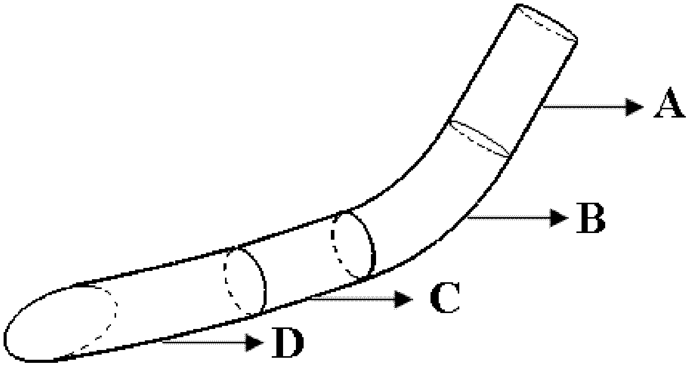
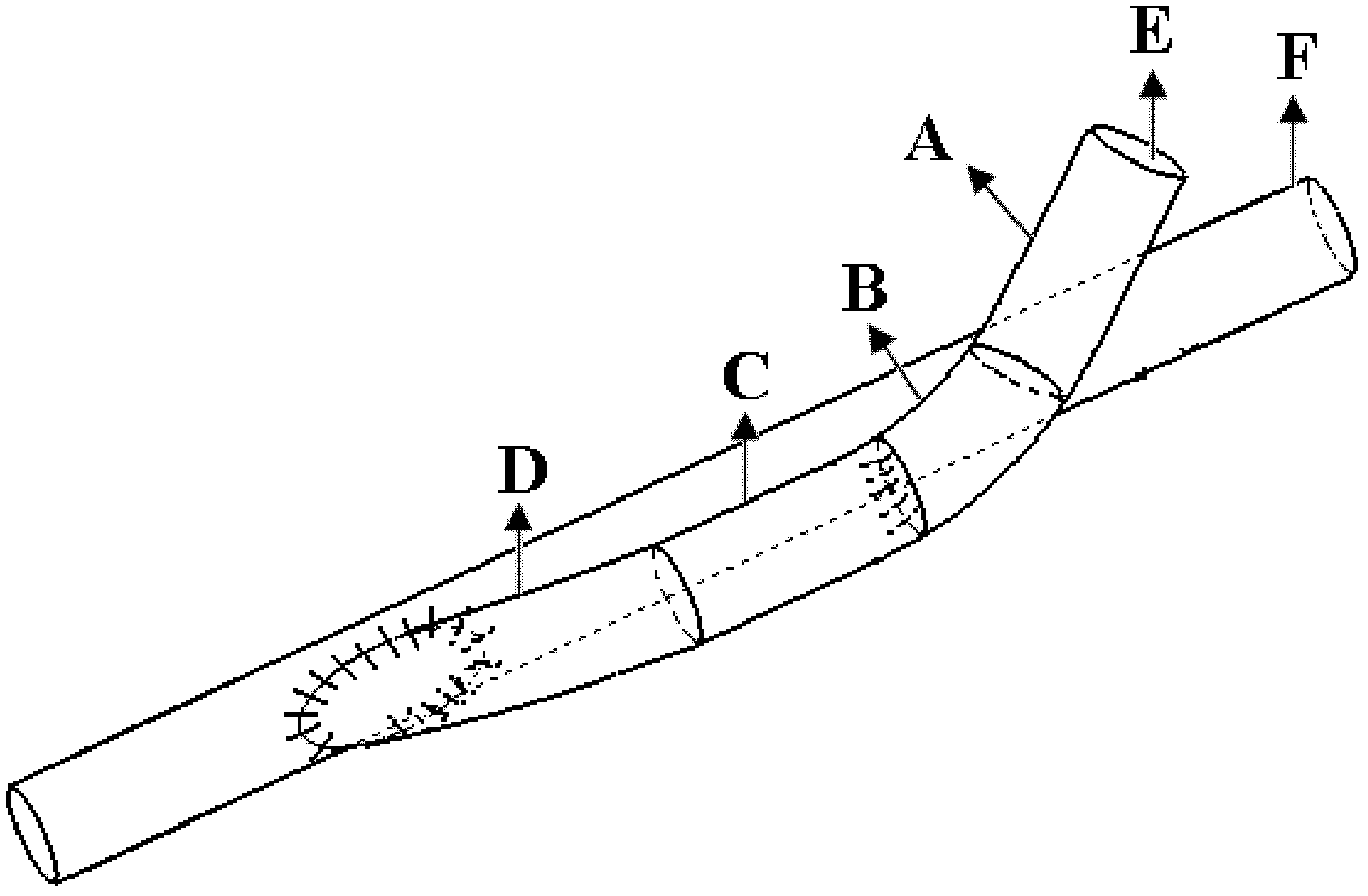
[0013] Such as figure 1 , figure 2 , image 3 As shown: the artificial blood vessel of the present invention is mainly composed of four parts: an ordinary artificial blood vessel part, a round corner turning transition part, a parallel blood vessel part, and a sutured edge part at the end. It is characterized in that the artificial bypass blood vessel has a rounded turning part, which can reduce the angle between the bypass blood vessel and the bypassed blood vessel to zero, so as to reduce the disturbance of blood flow at the bypass suture. By using the artificial blood vessel of the present invention for bypassing, the blood flows through the artificial common blood vessel part into the round corner transition part, and the included angle between the blood flow direction in the bypass blood vessel and the axial direction of the bypassed blo...


PUM


Abstract

The invention discloses an artificial blood vessel for realizing zero-angle bypass grafting, which is characterized by comprising an artificial bypass grafting blood vessel (E part in a figure), a common artificial blood vessel part (A in the figure), round-cornered transition part (B in the figure), a parallel blood vessel part (C in the figure) and a tail end stitched edge (D in the figure), wherein the four parts are combined into a whole. An F part in the figure is a sketch map of a blood vessel to be grafted with a bypass. Compared with the conventional artificial bypass grafting blood vessel, the artificial blood vessel has a round-cornered part which allows the blood flowing direction in the bypass grafting blood vessel to gradually reduce an included angle with the axial direction of the blood vessel to be grafted with the bypass to zero degree and to be parallel to the axial direction of the blood vessel, so that the bypass grafting blood vessel is stitched with the blood vessel to be grafted with the bypass in a zero-angle mode; therefore, the disturbance of blood flow in a bypass grafting stitching part is minimized, and the restenosis of blood vessel after the bypass grafting is inhibited effectively.

Description

technical field [0001] The invention relates to an artificial blood vessel, more specifically, an artificial blood vessel used to assist blood vessel bypass. (if attached image 3 shown). Background technique [0002] Vascular bypass surgery is widely used to treat patients with occluded vessels. By bypassing, the blood flow in the blood vessel bypasses the occluded blood vessel and flows to the distal end, thereby restoring the blood supply to the remote organ. At present, the materials used for bypass are basically the patient's own blood vessels or artificial blood vessels. However, vascular intimal hyperplasia has become a major reason for the late failure of medium and small vessel surgery after bypass surgery. Vascular bypass surgery mostly adopts upstream and downstream suturing methods. Although intimal hyperplasia can occur at both upstream and downstream sutures of implanted vessels, for upstream and downstream bypass operations, the intimal hyperplasia produce...

Claims


Application Information

Patent Timeline
IPC IPC(8): A61F2/06
Inventor 陈增胜邓小燕樊瑜波
Owner BEIHANG UNIV
Learn More