Solenoid valves for fluid control

A technology for controlling fluids and solenoid valves, applied in the field of solenoid valves, can solve problems such as electromagnetic function damage of solenoid valves, achieve the effects of improving flow conditions, reducing pressure and flow speed, improving electromagnetic characteristic curves and hydraulic damping conditions

Active Publication Date: 2015-11-25
ROBERT BOSCH GMBH
View PDF13 Cites 0 Cited by
  • Summary
  • Abstract
  • Description
  • Claims
  • Application Information

AI Technical Summary

Problems solved by technology

However, large gaps significantly impair the electromagnetic function of the solenoid valve

Method used


Image

  • Solenoid valves for fluid control
  • Solenoid valves for fluid control
  • Solenoid valves for fluid control

Examples


Embodiment Construction

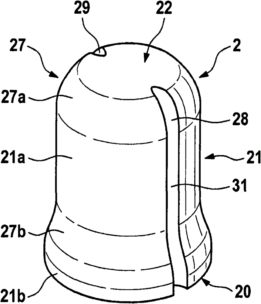
[0018] Next refer to figure 1 and figure 2 The solenoid valve for controlling fluid according to the first preferred embodiment of the present invention will be described in detail.

[0019] figure 1 A schematic sectional view of an armature 2 of a solenoid valve 1 for controlling a fluid according to a first embodiment of the present invention is shown.

[0020] as by figure 1 It can be seen that the armature comprises a bottom region 20 , a side region 21 and a top region 22 and is connected to the valve element 3 of the solenoid valve 1 at the bottom region 20 . The armature 2 is accommodated in a pot-shaped armature housing part 23 . A flow path 26 is formed between the armature 2 and the armature housing part 23 . The flow sequences in the flow path 26 are marked with arrows P1 , P2 and P3 and run from the lower armature chamber 24 to the upper armature chamber 25 and back to the lower armature chamber 24 . Between the top region 22 and the side region 21 of the ar...


PUM


Abstract

A solenoid valve for controlling a fluid includes an armature having a base region, a lateral region and a head region. The solenoid valve includes a valve member connected to the armature. The solenoid valve further includes an armature casing component in which the armature is positioned. A flow path is formed between the armature and the armature casing component, the flow path extending from a lower armature space to an upper armature space and back to the lower armature space. A junction region is arranged between the head region and the lateral region. The junction region has at least one groove formed therein to facilitate an overflow between the lateral region and the head region.

Description

technical field [0001] The invention relates to a solenoid valve for controlling fluid. Background technique [0002] Such solenoid valves for controlling fluids are known in various designs from the prior art, in particular, for example, as outlet valves for ABS / TCS / ESP systems in motor vehicles. These solenoid valves have an armature arranged axially movable in a valve housing. In this case, a relatively large gap is provided between the armature and the valve housing, which gap enables a fluid flow between the upper armature chamber and the lower armature chamber when the solenoid valve is actuated. However, large gaps significantly impair the electromagnetic function of the solenoid valve. Contents of the invention [0003] In contrast, the solenoid valve according to the invention for controlling a fluid has the advantage that the flow through the armature chamber is significantly improved by the shape of the armature. According to the invention, this is achieved i...

Claims


Application Information

Patent Timeline
Patent Type & Authority Patents(China)
IPC IPC(8): F16K31/06
CPCF16K31/0693B60T8/363F16K27/00
Inventor A·卡尔M·安布罗西N·霍伊斯J·诺贝格S·施泰因加斯E·菲尔A·莱希勒G·施托克迈尔
Owner ROBERT BOSCH GMBH
Why Eureka
Try Eureka