
Mesh reinforcement automatic bending and moulding machine

A technology of forming machine and mesh reinforcement, applied in the field of mesh reinforcement automatic bending and forming machine, can solve the problems of high labor intensity, low efficiency, affecting process quality of online workers, and achieve high bending efficiency, reduced labor intensity, and bending The effect of reliable guarantee of bending quality

Active Publication Date: 2011-09-07
广州番禺于一金属加工有限公司
View PDF5 Cites 19 Cited by
  • Summary
  • Abstract
  • Description
  • Claims
  • Application Information

AI Technical Summary

Problems solved by technology

[0003] The above-mentioned processing methods have the following deficiencies: First, the degree of consistency of bending is difficult to guarantee, because even if the same worker, it is objectively difficult to achieve the same degree of bending and stretching of each mesh bar, which will affect the quality of subsequent processes, unless a regular bending machine is added. In order to make the folded mesh bars uniform, but this will increase the process steps and manpower; the second is that the labor intensity of the online workers is high and the efficiency is low
[0004] In view of the above-mentioned prior art, if there is a kind of special machine that can be suitable for bending mesh bars, the aforementioned problems can be solved, but there is no technical inspiration that can be used for reference in the published patents and non-patent literature. The applicant has made useful explorations, and the technical scheme to be introduced below is produced under this background

Method used


Image

  • Mesh reinforcement automatic bending and moulding machine
  • Mesh reinforcement automatic bending and moulding machine
  • Mesh reinforcement automatic bending and moulding machine

Examples


Embodiment Construction

[0020] In order to enable the examiners of the patent office, especially the public, to understand the technical essence and beneficial effects of the present invention more clearly, the applicant will describe in detail the following in the form of examples, but none of the descriptions to the examples is an explanation of the solutions of the present invention. Any equivalent transformation made according to the concept of the present invention which is merely formal but not substantive shall be regarded as the scope of the technical solution of the present invention.

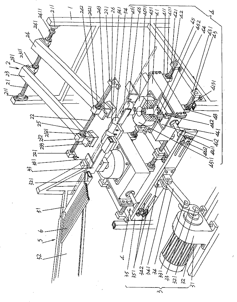
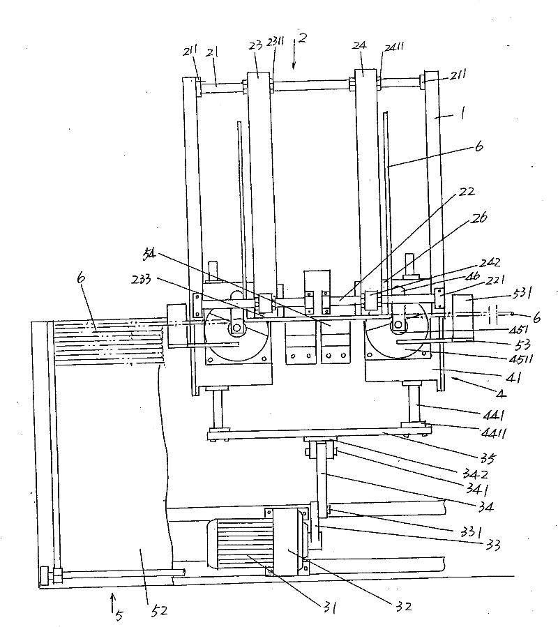
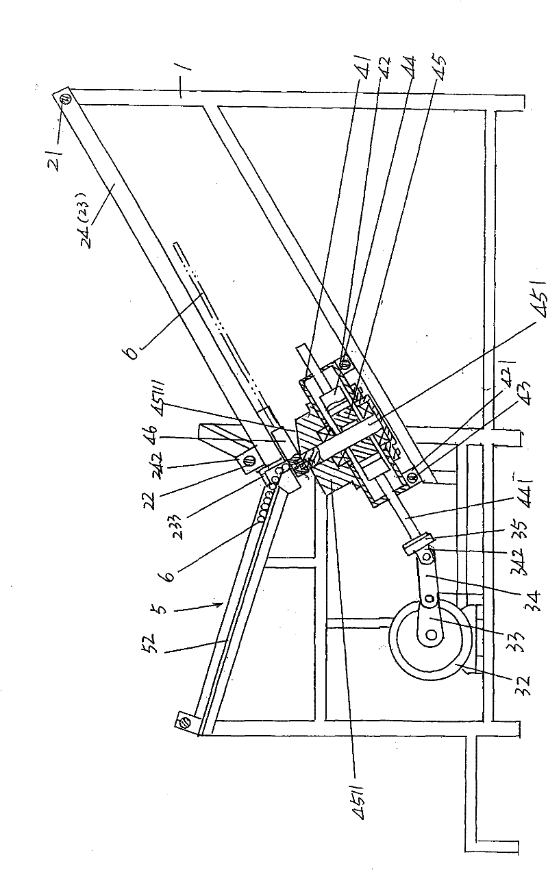
[0021] please see figure 1 , figure 2 and image 3 , at the right end of the given rack 1 (taking the current position as shown in the figure as an example) set by figure 1 The structure of static mold mechanism 2 schematically shown in detail, preferably but not absolutely limited to static mold mechanism 2 is as follows: comprise upper adjustment screw rod 21, lower adjustment screw rod 22, first static ...


PUM


Abstract

The invention relates to a mesh reinforcement automatic bending and moulding machine, belonging to the technical field of commercial facility processing machinery. The machine comprises a rack, a fixed die mechanism, a power mechanism and a moving die mechanism, wherein the fixed die mechanism is fixed on the rack and is arranged at one side of the rack, the moving die mechanism is arranged on the rack and is arranged between the fixed die mechanism and the power mechanism, one side of the moving die mechanism towards the power mechanism is connected with the power mechanism in a transmissionway, and one side of the moving die mechanism towards the fixed die mechanism is matched with the fixed die mechanism, thus a mesh reinforcement is bent. In the technical scheme, the fixed die mechanism and the moving die mechanism are arranged on the rack, and the moving die mechanism is connected with the power mechanism arranged on the rack, thus the power mechanism drives the moving die mechanism to act and the mesh reinforcement which enters into a gap between the fixed die mechanism and the moving die mechanism can be bent under the coordination of the fixed die mechanism. The machine provided by the invention has the advantages that the bending efficiency is high, the bending quality can be guaranteed, and the labour intensity of an operator can be reduced.

Description

technical field [0001] The invention belongs to the technical field of commercial facility processing machinery, and in particular relates to an automatic bending and forming machine for mesh reinforcement, which is used for folding the mesh reinforcement of mesh sheets such as hollowed-out supermarket trolleys, shopping baskets and fruit thinning trays that constitute commercial facilities. Bend into shape. Background technique [0002] As is known in the industry engaged in the development and production of commercial facilities, self-selection supermarkets and shopping malls are usually equipped with supermarket trolleys and shopping baskets that are temporarily used by customers when purchasing items. The mesh and the front, rear, left, and right meshes are processed. These meshes are usually composed of mesh bars (also called ribs) of specific specifications. In the production process, it is necessary to bend the mesh bar into a "U" shape, "L" shape or "mouth" shape ac...

Claims


Application Information

Patent Timeline
Patent Type & Authority Applications(China)
IPC IPC(8): B21F1/00B21F23/00
Inventor 李巍刘向蕾张廷威
Owner 广州番禺于一金属加工有限公司
Learn More