Fuel injection valve for internal combustion engine and method of manufacturing the same

A technology of fuel injection valve and internal combustion engine, which is applied to fuel injection device, special fuel injection device, internal combustion piston engine, etc., can solve the problems of rising cost, increasing the number of injection holes, complicated manufacturing process, etc., and achieve the effect of inhibiting adhesion

Inactive Publication Date: 2011-08-24
TOYOTA JIDOSHA KK
View PDF8 Cites 2 Cited by
  • Summary
  • Abstract
  • Description
  • Claims
  • Application Information

AI Technical Summary

Problems solved by technology

However, if the diameter of the injection hole is reduced, the angle at which the fuel diffuses from the injection hole (spray angle) becomes smaller. Therefore, in order to make the air-fuel ratio uniform, it is necessary to increase the number of injection holes.
For such a fuel injection valve, the manufacturing process becomes complicated and the cost increases

Method used


Image

  • Fuel injection valve for internal combustion engine and method of manufacturing the same
  • Fuel injection valve for internal combustion engine and method of manufacturing the same
  • Fuel injection valve for internal combustion engine and method of manufacturing the same

Examples


Embodiment 1

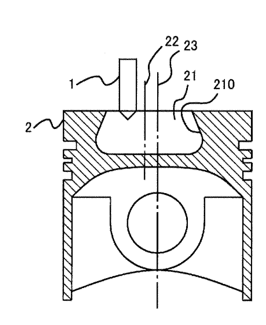
[0039] figure 1 is a diagram showing the positional relationship between the fuel injection valve 1 and the piston 2 according to the present embodiment. Should figure 1 It is a cross-sectional view of the piston 2 cut along the cylinder axis when the piston 2 is located near the top dead center. A combustion chamber 21 is formed on the upper surface of the piston 2 so that a part of the upper surface is recessed into the piston 2 . The combustion chamber 21 is formed such that the cross section formed by the plane perpendicular to the central axis of the piston 2 is circular. Also, the central axis 22 of the combustion chamber 21 and the central axis 23 of the piston 2 are parallel and spaced apart.

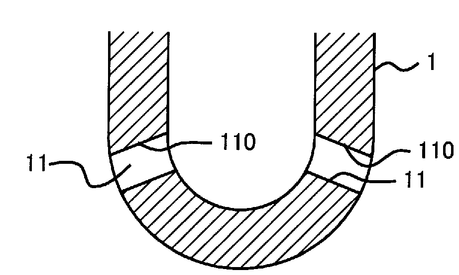
[0040] The fuel injection valve 1 is mounted spaced apart from the central axis 22 of the combustion chamber 21 . here, figure 2 is a longitudinal sectional view of the vicinity of the front end of the fuel injection valve 1 according to the present embodiment. The fuel i...


PUM


Abstract

A fuel injection valve for an internal combustion engine is adapted such that the smaller the distance from a nozzle hole to a combustion chamber wall surface, the greater the angle of injection of fuel. The fuel injection valve (1) has nozzle holes and injects fuel into the combustion chamber of the internal combustion engine. The surface roughness of a nozzle hole wall surface is set for each nozzle hole according to the distance between the nozzle hole and the combustion chamber wall surface (210). The degree of turbulence of the flow of fuel changes depending on the surface roughness, and this changes the angle of fuel injection.

Description

technical field [0001] The present invention relates to a fuel injection valve for an internal combustion engine and a manufacturing method thereof. Background technique [0002] A fuel injection valve for directly injecting fuel into a cylinder of an internal combustion engine may not be installed on the central axis of the combustion chamber due to the installation positions of the intake valve and the exhaust valve. For example, in an internal combustion engine in which one intake valve and one exhaust valve are arranged for each cylinder, the intake valve and the exhaust valve are formed to be large in order to ensure the flow rates of intake air and exhaust gas. Therefore, it is necessary to deviate the installation position of the fuel injection valve from the central axis of the cylinder. On the other hand, when the combustion chamber is formed on the upper surface of the piston, the position where the combustion chamber can be formed is limited in the structure of t...

Claims


Application Information

Patent Timeline
IPC IPC(8): F02M61/18
CPCF02B23/0669Y02T10/125F02B23/066F02M2200/8092Y02T10/123F02M61/1806F02M2200/8069F02B2275/14F02M61/168F02B23/0636Y02T10/12
Inventor 桥诘刚
Owner TOYOTA JIDOSHA KK
Why Eureka
Try Eureka