
Electric paper shredder

A paper shredder, electric technology, applied in the direction of grain processing, etc., can solve the problem of not being able to put the paper to be shredded at any time, such as inconvenience, and achieve the effect of saving paper shredding time, reducing equipment energy consumption, and avoiding paper jams

Active Publication Date: 2011-08-17
ROYAL SOVEREIGN QINGDAO
View PDF6 Cites 9 Cited by
  • Summary
  • Abstract
  • Description
  • Claims
  • Application Information

AI Technical Summary

Problems solved by technology

The method of shredding paper from the bottom of the upper cover, such as Chinese Patent No. 200820151690.0 discloses a paper shredder, the cardboard is set at the lower part of the upper cover, and the method of shredding paper after folding the paper in half is adopted. The disadvantage is that it cannot be put in at any time. shredded paper
U.S. Patent Nos. US20060430121 and US20040866145 respectively disclose a paper shredder pallet capable of folding and shredding paper and a paper shredder capable of folding paper in half. At both ends of the paper mouth, the place where the shredded paper is folded in half is the middle of the paper. The disadvantage is that the second paper can only be shredded after one paper is shredded.
[0003] How to fold and shred multiple sheets of paper from the bottom of the upper cover, and add paper to be shredded at any time, so as to further improve shredding efficiency and save Energy, the current technology still has inconveniences and defects, and needs to be further improved urgently

Method used


Image

  • Electric paper shredder
  • Electric paper shredder
  • Electric paper shredder

Examples


Embodiment Construction

[0040] The technical solutions of the present invention will be described in detail below with reference to the accompanying drawings and preferred embodiments.

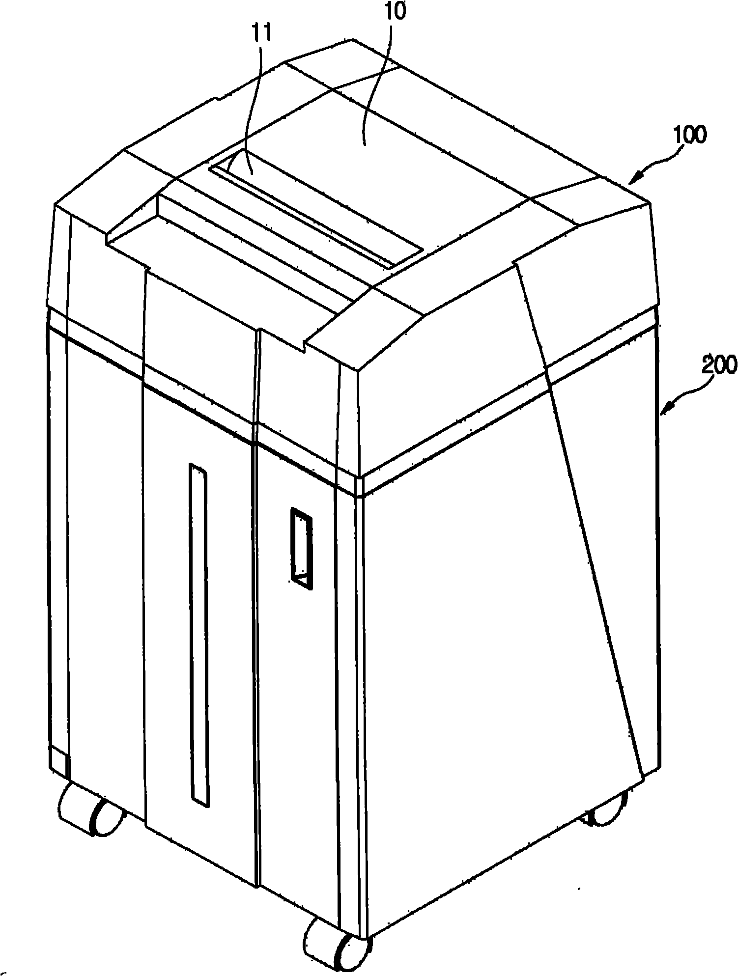
[0041] Such as figure 1 Shown is a three-dimensional structure schematic diagram of the electric shredder of the present invention. The main structure of the paper shredder of the present invention includes a shredding unit 100 and a box body 200. The shredding unit 100 is arranged above the box body 200, wherein an upper cover 10 is arranged on the upper part of the shredding unit 100, and the sides of the upper cover 10 and the shredder The outer sides of the paper part 100 are movably connected, and the upper cover 10 is provided with a manual paper feeding port 11 .

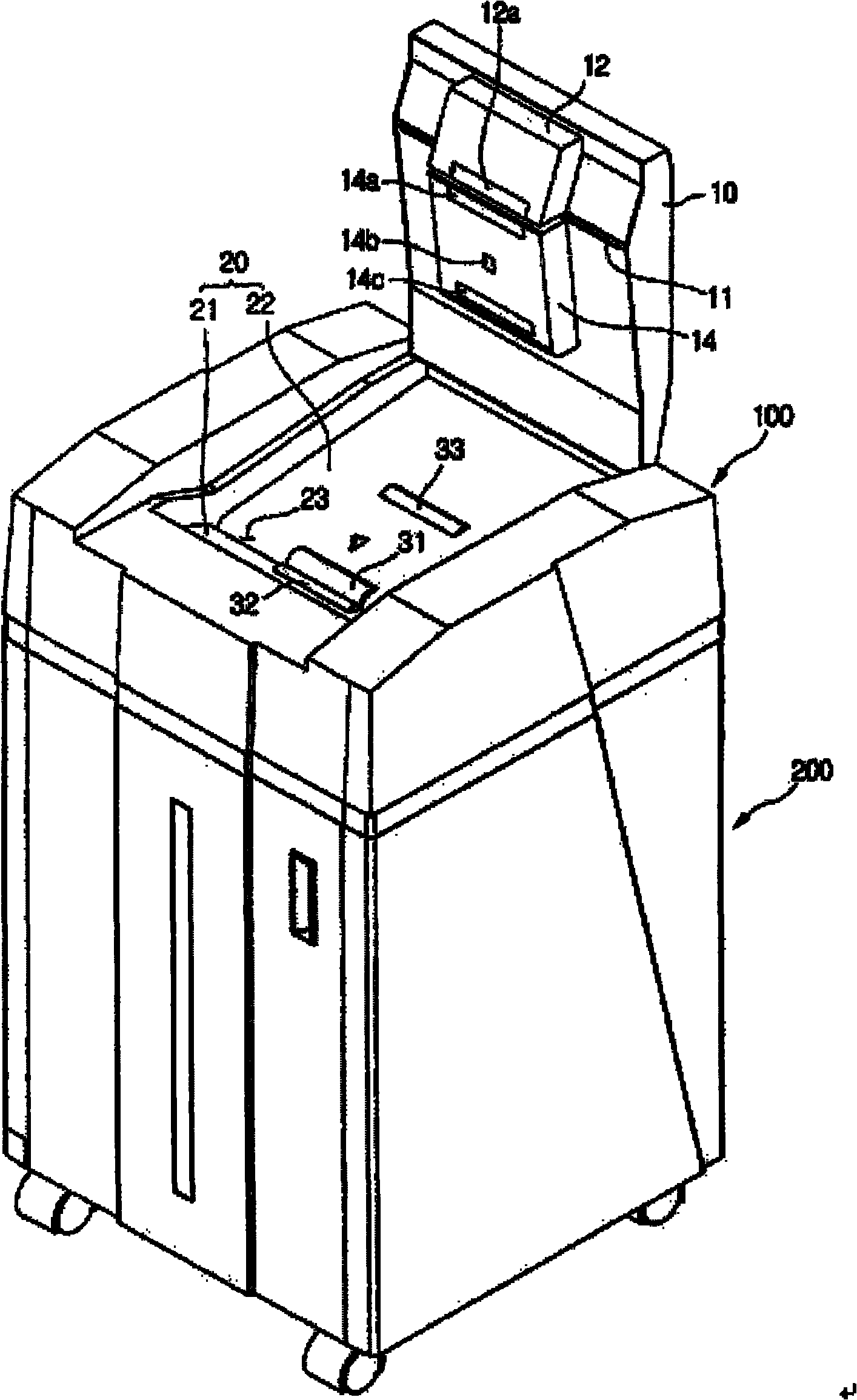
[0042] Such as figure 2 As shown, it is a three-dimensional structure schematic diagram of the electric shredder of the present invention with the upper cover opened. The paper supporting board 20 is arranged in the groove of the paper shredding...


PUM


Abstract

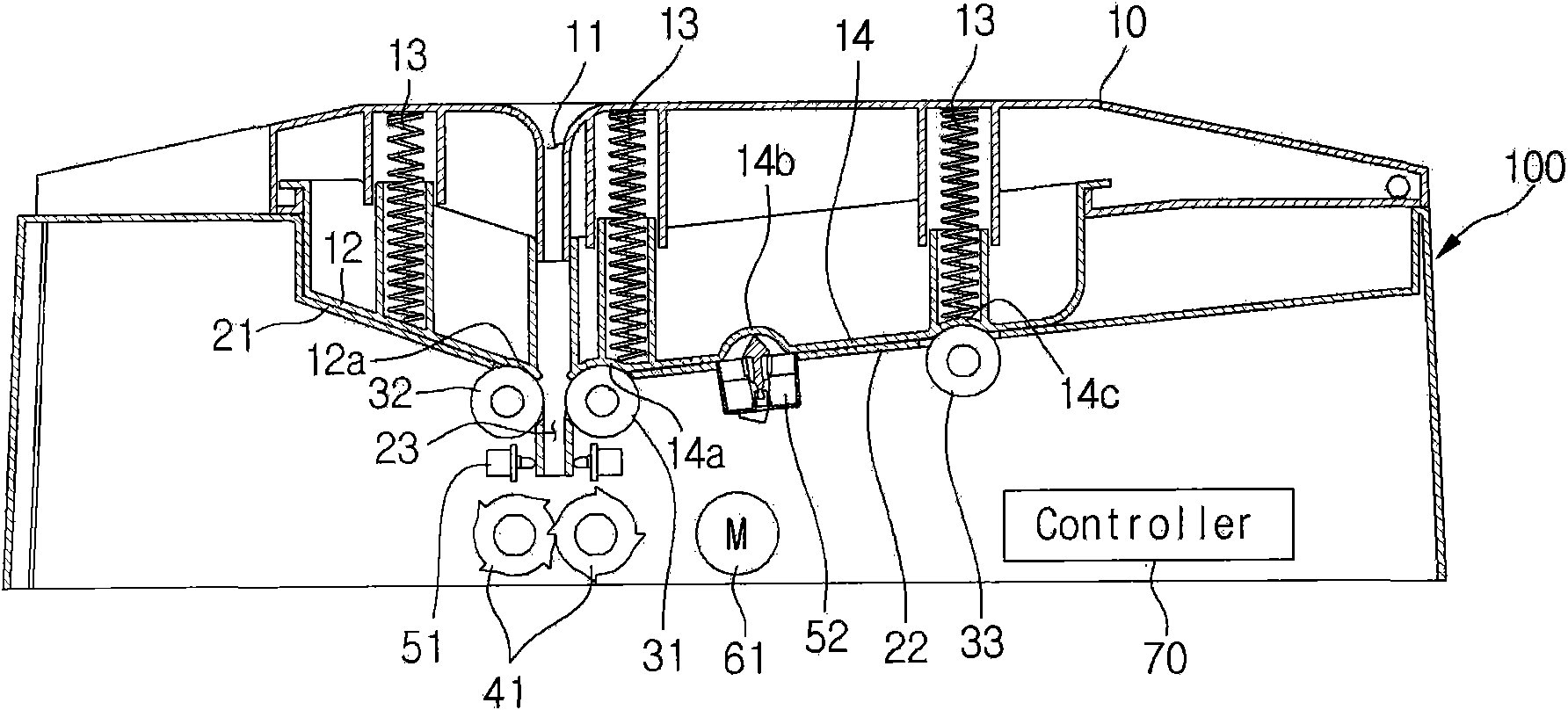
The invention discloses an electric paper shredder, which comprises a paper shredding part and a box body, wherein the paper shredding part is arranged at the upper part of the box body; the paper shredding part is provided with an upper cover, paper supporting plates and paper feeding rollers; the paper supporting plates are arranged at the lower part of the upper cover; the paper supporting plates comprise a first paper supporting plate and a second paper supporting plate with different lengths, and a paper shredding port is formed between the first paper supporting plate and the second paper supporting plate; the first paper supporting plate and the second paper supporting plate are provided with a paper feeding roller through groove respectively, and the paper feeding rollers are arranged at the two paper feeding roller through grooves respectively; and the second paper supporting plate is provided with a sensor through hole, and a paper accumulation sensor is arranged at the sensor through hole. The electric paper shredder can fold and crush a certain amount of paper, and can also be added with paper to be shredded at any time.

Description

technical field [0001] The invention belongs to the field of shredders, in particular to an electric shredder. Background technique [0002] A paper shredder is a daily office item that can quickly shred confidential documents. At present, the shredding methods of paper shredders can be divided into paper shredding from the top of the upper cover and paper shredding from the bottom of the upper cover; paper feeding and shredding from the top of the upper cover, such as Chinese Patent No. 97249670.X discloses a In the paper shredder, the paper support plate is arranged on the upper part of the upper cover, and the paper feed roller is arranged under the upper cover, and the pressure plate holds the paper against the paper feed roller, and the paper feed roller sends the paper to be shredded to the shredder roller. The method of shredding paper from the bottom of the upper cover, such as Chinese Patent No. 200820151690.0 discloses a paper shredder, the cardboard is set at the...

Claims


Application Information

Patent Timeline
Patent Type & Authority Applications(China)
IPC IPC(8): B02C18/08B02C18/16B02C18/22
Inventor 金鹤贤
Owner ROYAL SOVEREIGN QINGDAO
Learn More