Soil ventilating means and subterranean pollutant treatment system

A ventilation device and pollutant treatment technology, which is applied in the field of volatile organic pollution removal devices in unsaturated soil zones, can solve the problems of ineffective treatment of low-concentration pollution, and achieve the effects of simple structure, pollution removal, and low operating costs

Inactive Publication Date: 2013-11-13
湖南人居环境事业发展有限公司
View PDF0 Cites 3 Cited by
  • Summary
  • Abstract
  • Description
  • Claims
  • Application Information

AI Technical Summary

Problems solved by technology

In other words, existing technologies cannot effectively control such low-concentration pollution

Method used


Image

  • Soil ventilating means and subterranean pollutant treatment system
  • Soil ventilating means and subterranean pollutant treatment system
  • Soil ventilating means and subterranean pollutant treatment system

Examples


Embodiment Construction

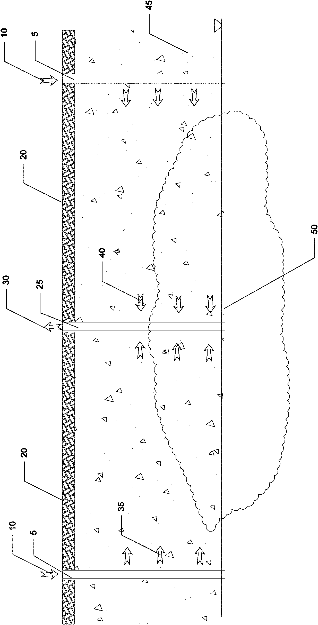
[0075] Such as Figure 3-Figure 11 , Figure 11A , Figure 11B As shown, the present invention provides a kind of soil ventilation device, and it comprises airtight chamber 70, and this airtight chamber 70 has inlet 701 and outlet 702, and this inlet 701 and outlet 702 can be as image 3 The one shown is one, and of course there can be more than one according to needs; a pair of one-way valves 60 are respectively installed on the inlet 701 and the outlet 702 to ensure that the gas flows in only one direction, and the one-way valve installed on the inlet The valve 60 is called an inlet one-way valve, and the one-way valve 60 installed at the outlet is called an exhaust one-way valve. The setting of the pair of one-way valves 60 makes the air flow only flow in one way from the inlet of the airtight chamber 70 , and flow out from the outlet of the airtight chamber 70 in one direction. In this way, when the temperature in the airtight chamber 70 changes, the thermal expansion a...


PUM


Abstract

A soil venting system driven by air thermal property is developed to deaf with tow concentration gaseous hazard materials in unsaturated zone of soil. A process utilizes the thermal driven soil venting system to create air gradient in the unsaturated zone of soil and force the gaseous hazard materials out the contaminated soil.

Description

technical field [0001] The present invention relates to a device for removing volatile organic pollution in unsaturated soil, in particular, relates to a soil ventilation device and an underground pollutant treatment system driven by the characteristics of air thermal expansion and cold contraction. Background technique [0002] The technology of removing pollution in the unsaturated zone of soil is already a very mature technology. These techniques can be grouped into two categories. One is to force air to flow through the pores in the soil, using the air to carry away those volatile pollutants. The other is to inject chemical or biological agents into the ground to accelerate the degradation of pollutants. Since the 1970s, these cleaning technologies have been widely used in the environmental protection industry. [0003] The means used in these methods, while sophisticated, are expensive. Whether it's mechanical devices that force air flow or various cleaning agents, ...

Claims


Application Information

Patent Timeline
Patent Type & Authority Patents(China)
IPC IPC(8): B09C1/06F16K15/20
CPCB09C1/005B09C1/06
Inventor 陈有志
Owner 湖南人居环境事业发展有限公司
Why Eureka
Try Eureka