
Device for testing zero distortion of carbon fiber member

A testing device and carbon fiber technology, which can be used in measurement devices, electrical devices, optical devices, etc., can solve the problem of low thermal expansion coefficient accuracy and so on

Inactive Publication Date: 2011-08-03
SHANGHAI SATELLITE ENG INST
View PDF0 Cites 6 Cited by
  • Summary
  • Abstract
  • Description
  • Claims
  • Application Information

AI Technical Summary

Problems solved by technology

[0005] In order to solve the problem that the accuracy of the thermal expansion coefficient of the existing carbon fiber components is not high, the purpose of the present invention is to provide a testing device for zero deformation of the carbon fiber components
The present invention can solve the detection problem of zero deformation performance of carbon fiber material components in the working environment with large temperature difference changes

Method used


Image

  • Device for testing zero distortion of carbon fiber member
  • Device for testing zero distortion of carbon fiber member

Examples


Embodiment Construction

[0014] Preferred embodiments of the present invention will be described below in conjunction with the accompanying drawings.

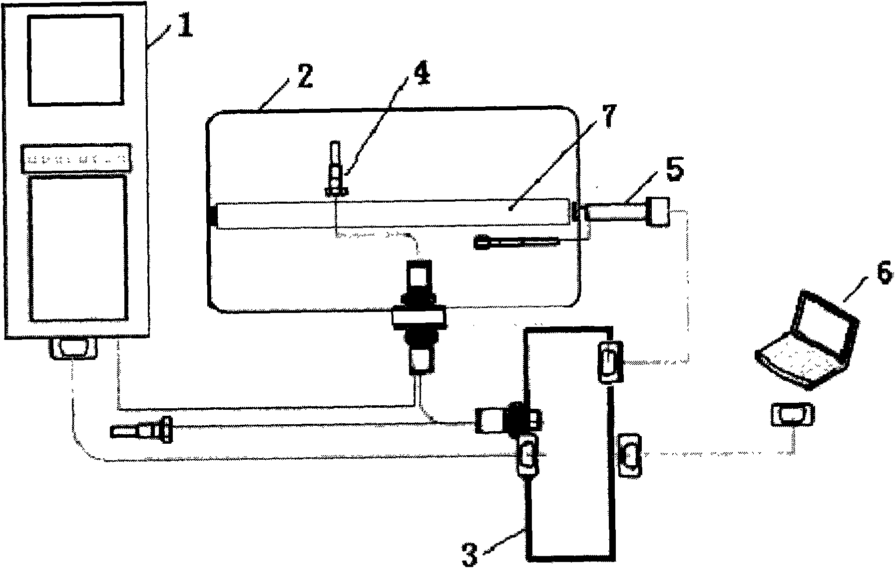
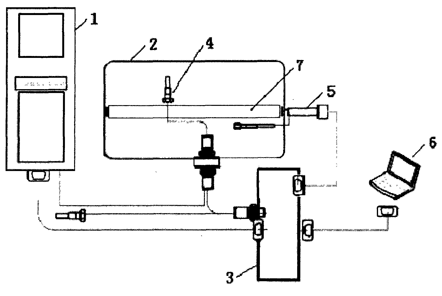
[0015] The accompanying drawing is a schematic structural diagram of the carbon fiber component zero deformation testing device of the present invention, as shown in the embodiment of the accompanying drawing, the device includes: a high and low temperature control cabinet [1], a high and low temperature test box [2], a measurement and control system control box [3] ], temperature sensor [4], MTI2000 optical fiber displacement sensor [5], computer control and analysis system [6] and carbon fiber components [7].

[0016] The above-mentioned carbon fiber component [7] is put into the high and low temperature test chamber [2], one end is fixed, and the other end is movable, and the extension of the movable end is measured by the MTI2000 optical fiber displacement sensor [5]. The optical fiber displacement sensor [5] is a non-contact type, and the displace...


PUM


Abstract

The invention discloses a device for testing zero distortion of a carbon fiber member, which comprises a high-low temperature control cabinet [1], a high-low temperature testing box [2], a measurement system control box [3], a temperature sensor [4], an MTI2000 optical fiber displacement sensor [5], a computer control and analysis system [6] and a carbon fiber member [7]. The device solves the problem of poor precision of detecting a thermal expansion coefficient of the traditional carbon fiber member. By adopting the device for testing the zero distortion of the carbon fiber member, the detection problem of zero distortion performance of the carbon fiber material member in a working environment with larger temperature difference variations can be solved. The device for testing the zero distortion of the carbon fiber member has the advantages of simpleness and convenience for operation, high detection precision and low equipment cost.

Description

technical field [0001] The invention relates to a deformation detection device, in particular to a test device for detecting the zero deformation state of a carbon fiber component with a large temperature change under an operating temperature field. Background technique [0002] Satellites operating in geosynchronous orbit, because there is no protection of the atmosphere, the ambient temperature changes greatly. The temperature on the sunny side can be as high as hundreds of degrees, but the temperature on the back side is tens of degrees Celsius below zero. Therefore, satellites operating in this environment will cause dimensional changes in the satellite structure due to thermal expansion of materials. However, considering the technical requirements of certain components and instruments of the satellite, it is hoped that the stability of the satellite structure will be good. Therefore, such components will be made of zero-deformation carbon fiber materials. However, the ...

Claims


Application Information

Patent Timeline
IPC IPC(8): G01B21/32G01B11/02G01K7/18
Inventor 顾志悦宋东平
Owner SHANGHAI SATELLITE ENG INST
Learn More