
Equipment and method for controlling rail pressure of high-pressure rail-shared pipe cavity for high-pressure rail-shared fuel system

A high-pressure common rail and fuel system technology, applied in electrical control, mechanical equipment, engine control, etc., can solve problems such as errors, affecting the consistency of fuel injection in each cylinder of the engine power, and achieve the effect of reducing calibration work

Active Publication Date: 2011-08-03
WEICHAI POWER CO LTD
View PDF5 Cites 15 Cited by
  • Summary
  • Abstract
  • Description
  • Claims
  • Application Information

AI Technical Summary

Problems solved by technology

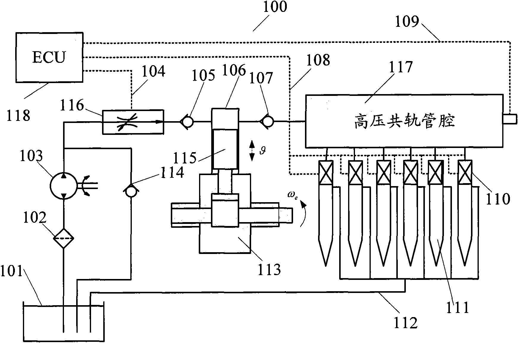
In addition, with this existing engine high-pressure common-rail fuel system control strategy, under certain operating conditions of the engine, there is a large gap between the actual measured value of the fuel pressure in the high-pressure common-rail tube cavity and the target value of the fuel pressure. Large deviation, which leads to a large error between the actual fuel injection quantity and the fuel target injection quantity in the high-pressure common rail fuel system of the engine, which directly affects the power of the engine and the consistency of fuel injection of each cylinder

Method used


Image

  • Equipment and method for controlling rail pressure of high-pressure rail-shared pipe cavity for high-pressure rail-shared fuel system
  • Equipment and method for controlling rail pressure of high-pressure rail-shared pipe cavity for high-pressure rail-shared fuel system
  • Equipment and method for controlling rail pressure of high-pressure rail-shared pipe cavity for high-pressure rail-shared fuel system

Examples


Embodiment Construction

[0030] The principle and spirit of the present invention will be described below with reference to several exemplary embodiments. It should be understood that these embodiments are given only to enable those skilled in the art to better understand and implement the present invention, rather than to limit the scope of the present invention in any way.

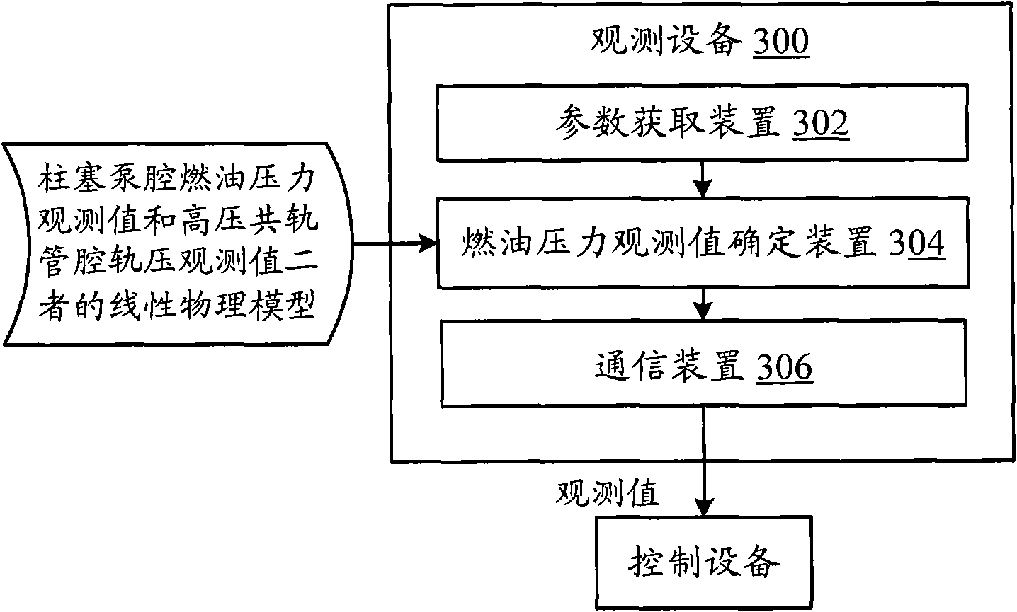
[0031] According to an embodiment of the present invention, a device and method for controlling the rail pressure of a high-pressure common-rail lumen of an engine high-pressure common-rail fuel system are proposed. Additionally, an apparatus and method for observing fuel pressure to cooperate with an apparatus and method for controlling rail pressure is provided.

[0032]Additionally, as used herein, the term "parameter" refers to any value of a physical quantity that is indicative of the (target or actual) physical state or operating condition of the engine. Also, herein, "parameter" and the physical quantity it represents ma...


PUM


Abstract

The invention provides equipment and a method for controlling rail pressure of a high-pressure rail-shared pipe cavity for an engine high-pressure rail-shared fuel system. The equipment comprises a working condition acquiring device, an equivalent cross sectional area determining device of a fuel gauging valve and a signal generating device, wherein the working condition acquiring device is used for acquiring working conditions relevant to the engine high-pressure rail-shared fuel system; the equivalent cross sectional area determining device of the fuel gauging valve is coupled to the working condition acquiring device and used for determining the equivalent cross sectional area of the fuel gauging valve by using a linear physical model according to the acquired working conditions and the rail pressure target value of the high-pressure rail-shared pipe cavity; and the signal generating device is coupled to the equivalent cross sectional area determining device of the fuel gauging valve and used for generating driving signals for controlling the equivalent cross sectional area of the fuel gauging valve according to the determined equivalent cross sectional area of the fuel gauging valve.

Description

technical field [0001] Embodiments of the present invention generally relate to the field of engines, and more specifically, to a device and method for controlling the rail pressure of a high-pressure common-rail lumen of an engine's high-pressure common-rail fuel system. Background technique [0002] The fuel pressure control in the existing engine high-pressure common rail fuel system adopts a PID (proportional-integral-derivative) type control strategy, which requires a lot of calibration work. In addition, with this existing engine high-pressure common-rail fuel system control strategy, under certain operating conditions of the engine, there is a large gap between the actual measured value of the fuel pressure in the high-pressure common-rail tube cavity and the target value of the fuel pressure. This leads to a large error between the actual fuel injection quantity and the fuel target injection quantity in the high-pressure common rail fuel system of the engine, which d...

Claims


Application Information

Patent Timeline
IPC IPC(8): F02D41/38F02D41/14
Inventor 胡广地孙少军佟德辉
Owner WEICHAI POWER CO LTD
Learn More