
Cooling fan and rotor thereof

A heat dissipation fan and rotor technology, which is applied to components of pumping devices for elastic fluids, non-variable pumps, pump devices, etc., can solve problems such as loud noise and limited fan heat dissipation performance, and achieve increased air volume and supplementary Pressure, swirl reduction effect

Inactive Publication Date: 2011-07-27
ZHONGSHAN YUNCHUANG INTELLECTUAL PROPERTY SERVICE CO LTD
View PDF5 Cites 10 Cited by
  • Summary
  • Abstract
  • Description
  • Claims
  • Application Information

AI Technical Summary

Problems solved by technology

However, this kind of fan has the following problems: 1. In order to ensure the normal operation of the rotor, there must be a certain gap between the end of the fan blade and the fan frame, so the size of the fan blade is limited in a certain assembly space, thereby limiting the size of the fan blade. 2. When the fan is running at high speed, one side of each fan blade is formed as the windward side, and the opposite side is formed as the leeward side, and negative pressure is formed in the area adjacent to the leeward side, so the airflow usually tends to It flows from the windward side of the fan blade to the negative pressure area through the end of the fan blade, that is, a vortex is generated, resulting in a large noise

Method used


Image

  • Cooling fan and rotor thereof
  • Cooling fan and rotor thereof
  • Cooling fan and rotor thereof

Examples


Embodiment Construction

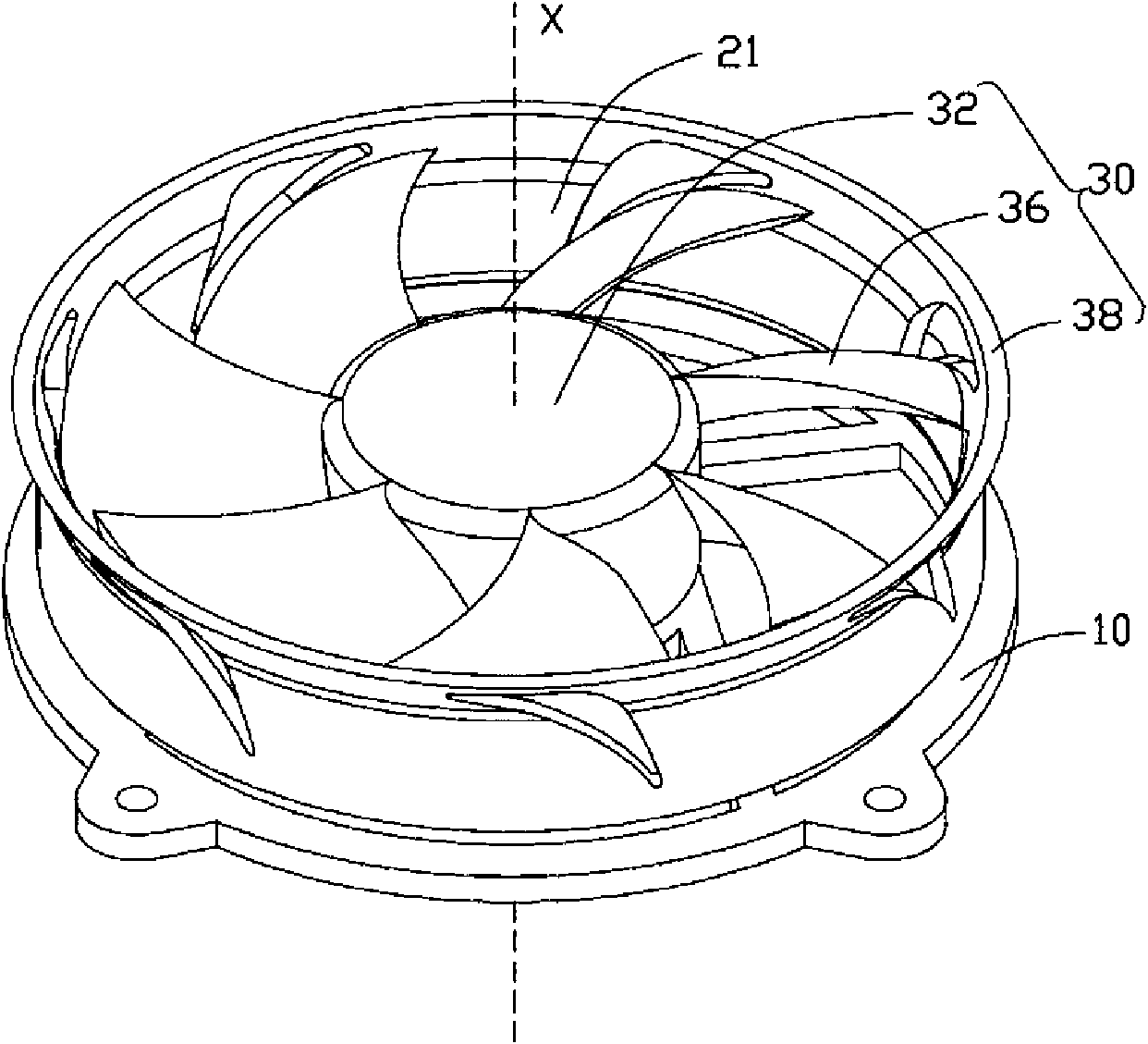
[0014] see figure 1 , the cooling fan includes a base 10, a stator (not shown) mounted on the base 10, and a rotor 30 mounted on the periphery of the stator.

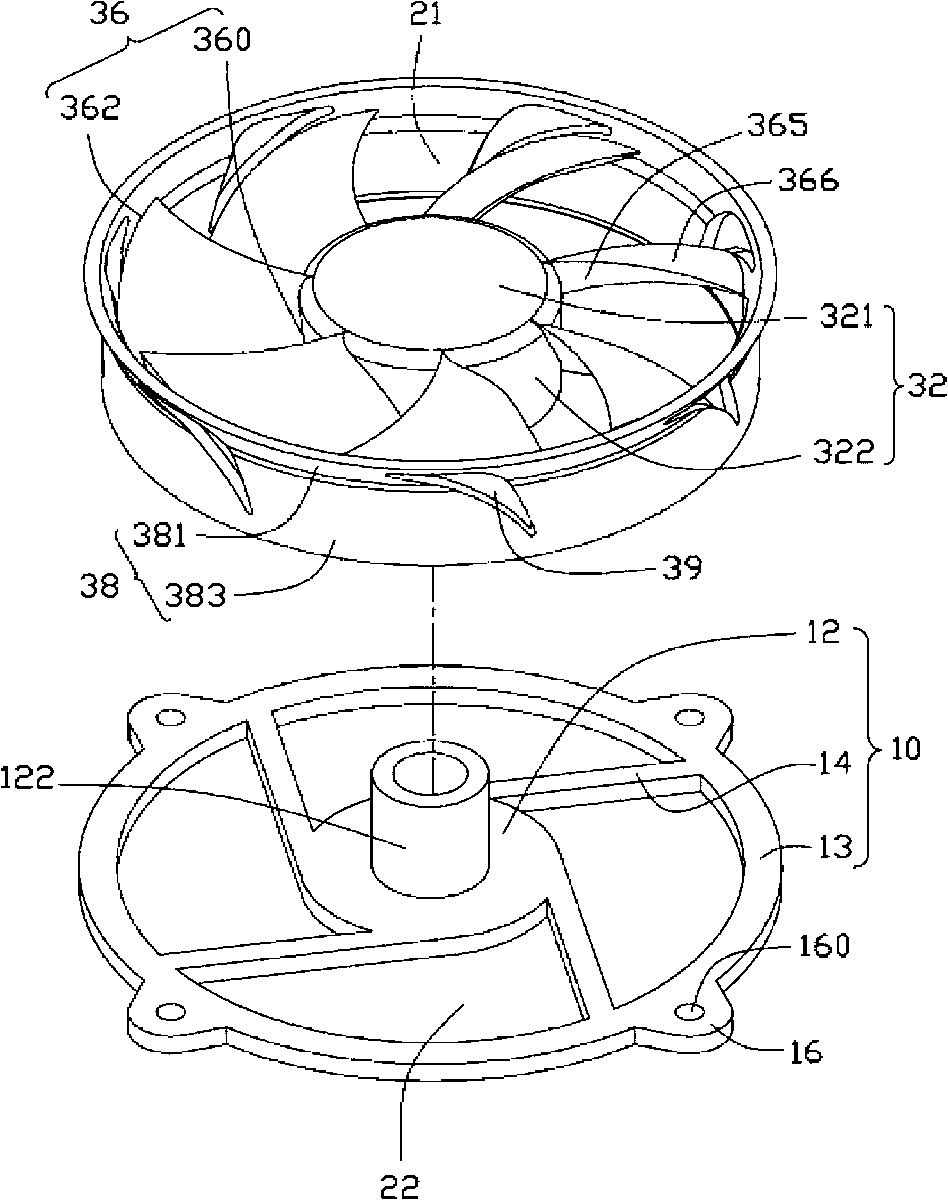
[0015] Please also see figure 2 The base 10 includes a circular support portion 12, an annular locking portion 13 spaced from and concentric with the support portion 12, and a number extending outward from the periphery of the support portion 12 to connect the support portion 12 and the locking portion 13. root ribs14. The base 10 forms an air outlet 22 between the supporting portion 12 and the locking portion 13 . The center of the supporting portion 12 protrudes upwards to form a central column 122 , and a bearing (not shown) is accommodated in the central column 122 . The locking portion 13 protrudes horizontally outward from the outer periphery to form a plurality of positioning portions 16 . The positioning portions 16 are arranged at equal intervals along the circumferential direction of the locking portion 1...


PUM


Abstract

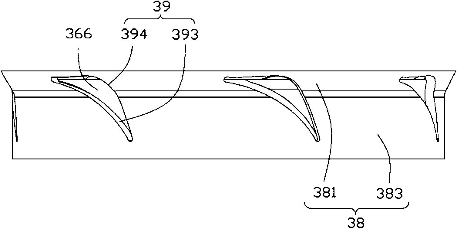
The invention relates to a cooling fan which comprises a base and a rotor arranged on the base; an air inlet and an air outlet are respectively formed at the two sides along the axial direction of the cooling fan; the rotor comprises a wheel hub and a plurality of fan blades arranged at the periphery of the wheel hub; each fan blade comprises a windward side and a leeward side opposite to the windward side; the rotor also comprises a ring-shaped wall which is arranged at the periphery of the fan blades and connected with the outer ends of the fan blades; a through hole is formed between every two adjacent fan blades on the ring-shaped wall; and the through hole is close to the rotating direction of the rotor and is arranged on the leeward side of the fan blade positioned in the front.

Description

technical field [0001] The invention relates to a heat dissipation fan, in particular to a heat dissipation fan suitable for heat dissipation of electronic components and a rotor thereof. Background technique [0002] With the rapid development of electronic technology, the running speed of heating electronic components such as the central processing unit is getting faster and faster, and the heat generated during operation also increases accordingly. In order to dissipate the heat to ensure the normal operation of electronic components, the industry uses fans to Electronic components dissipate heat. A traditional fan usually includes a stator, a rotor, and a frame for accommodating the stator and the rotor. The rotor includes a hub and a number of fan blades arranged on the periphery of the hub. When energized, the magnetic field generated by the stator interacts with the rotor. The role is to drive the rotor to rotate at a high speed relative to the stator and the fan fra...

Claims


Application Information

Patent Timeline
Patent Type & Authority Applications(China)
IPC IPC(8): F04D29/32F04D29/38F04D29/66
CPCF04D29/164F04D29/384F04D29/681F04D25/0613
Inventor 查新祥余业飞郭哲豪
Owner ZHONGSHAN YUNCHUANG INTELLECTUAL PROPERTY SERVICE CO LTD
Learn More