Video transmission method and system and optical network equipment
A technology of optical network equipment and video transmission, which is applied in the field of communication, can solve the problem of high implementation requirements, and achieve the effect of reducing implementation requirements
- Summary
- Abstract
- Description
- Claims
- Application Information
AI Technical Summary
Problems solved by technology
Method used
Image
Examples
Embodiment 1
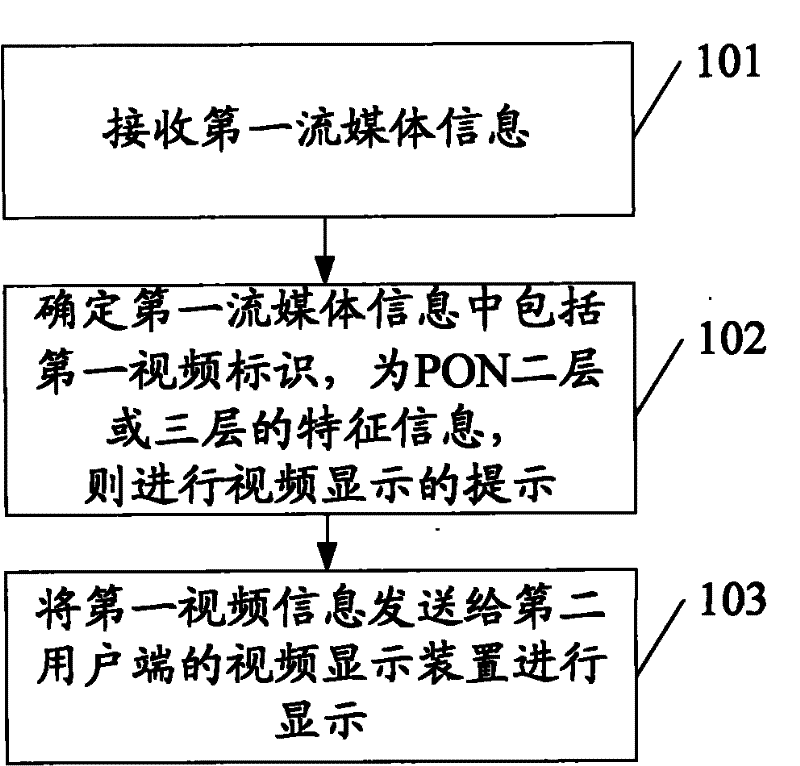
[0036] A video transmission method, the method of the embodiment of the present invention is applicable to such as figure 1 In the structural system shown, the video acquisition devices (such as cameras, etc.), video display devices (such as televisions, monitors, etc.) (such as ONU or ONT) connected. The execution subject of the video transmission method in this embodiment is the second user end optical network device, and the flow chart is as follows figure 2 shown, including:
[0037] Step 101, the optical network equipment of the second user end receives the first streaming media information sent by the first user end;
[0038] It can be understood that, in this embodiment, the first streaming media information is transmitted according to the session connection after the user paging device at the first user end establishes a session connection with the user paging device at the second user end.
[0039] Step 102, the optical network device at the second user end determ...
Embodiment 2
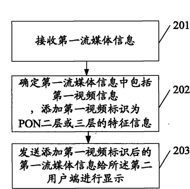
[0046] A video transmission method, the method of the embodiment of the present invention is applicable to such as figure 1 In the structural system shown, the video acquisition devices (such as cameras, etc.), video display devices (such as televisions, monitors, etc.) (such as ONU or ONT) connected. The execution subject of the video transmission method in this embodiment is the first user end optical network device, and the flow chart is as follows image 3 shown, including:
[0047] Step 201, the optical network equipment at the first user end receives the first streaming media information collected by the terminal device at the first user end;
[0048] It can be understood that, in this embodiment, the first streaming media information is transmitted according to the session connection after the user paging device at the first user end establishes a session connection with the user paging device at the second user end.
[0049] Step 202, the first client optical networ...
Embodiment 3
[0057] A video transmission method, the method of the embodiment of the present invention is applicable to such as figure 1 In the structural system shown, the video acquisition devices (such as cameras, etc.), video display devices (such as televisions, monitors, etc.) In this embodiment, the optical network device is an ONT or an ONU. The flowchart of the video transmission method in this embodiment is as follows Figure 4 shown, including:
[0058] Step 301, the ONT / ONU of the first user end receives the first streaming media information collected by the terminal device;
[0059] It can be understood that the first streaming media information is transmitted according to the session connection after the calling user paging device of the first user end establishes a session connection with the called user paging device of the first user end. The video information in the first media stream information can be collected by the video collection device of the first user end, an...
PUM
 Abstract
Description
Claims
Application Information
 - R&D Engineer
- R&D Manager
- IP Professional
- Industry Leading Data Capabilities
- Powerful AI technology
- Patent DNA Extraction
Browse by: Latest US Patents, China's latest patents, Technical Efficacy Thesaurus, Application Domain, Technology Topic, Popular Technical Reports.
© 2024 PatSnap. All rights reserved.Legal|Privacy policy|Modern Slavery Act Transparency Statement|Sitemap|About US| Contact US: help@patsnap.com


