Labyrinth type regulating valve pressure reducing device

A technology of pressure reducing device and regulating valve, applied in valve device, valve device for absorbing fluid energy, valve details, etc., can solve the problems of low pressure reducing efficiency, complicated processing of pressure reducing device, expensive production cost, etc. The effect of steam turbid noise, convenient processing and cost saving

Active Publication Date: 2011-07-20
SUZHOU DELAN ENERGY TECH
View PDF7 Cites 1 Cited by
  • Summary
  • Abstract
  • Description
  • Claims
  • Application Information

AI Technical Summary

Problems solved by technology

[0005] The technical problem to be solved by the present invention is to provide a labyrinth regulating valve decompression device to overcome the disadvantages of the prior art, such as complex processing of the decompression device, low decompression efficiency, and high production cost.

Method used


Image

  • Labyrinth type regulating valve pressure reducing device
  • Labyrinth type regulating valve pressure reducing device
  • Labyrinth type regulating valve pressure reducing device

Examples


Embodiment Construction

[0030] Below in conjunction with accompanying drawing and embodiment, the specific embodiment of the utility model is described in further detail. The following examples are used to illustrate the utility model, but not to limit the scope of the utility model.

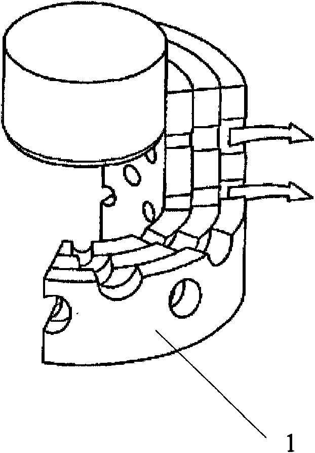
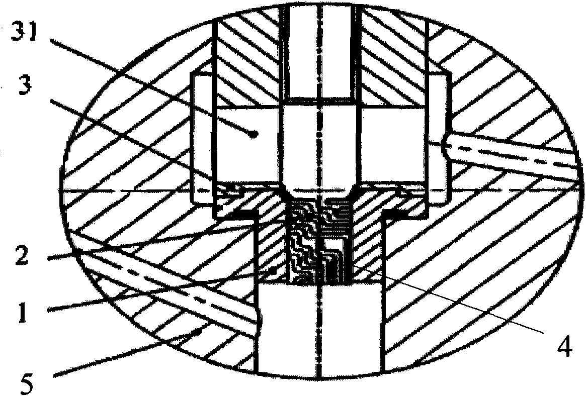
[0031] refer to Figure 3-Figure 5 , The labyrinth regulating valve pressure reducing device of the embodiment of the utility model includes a valve seat 1, a valve core 2 and a sleeve 3, the valve core 2 is located inside the valve seat 1, and the annulus of the valve core 2 has several grooves 4 in the axial direction. , the groove 4 has at least one curved portion, and the curved portion is rounded. The sleeve 3 is sleeved on the periphery of the valve core 2 , and the sleeve 3 has a window 31 whose height is equal to or greater than the length of the groove 4 . The groove 4 has an inlet and an outlet, the direction of the bending portion is not limited in the groove 4 , and the outlets of the groove all face the ...


PUM


Abstract

The invention relates to the technical field of control over fluids with high pressure differences, in particular to a labyrinth type regulating valve pressure reducing device. The labyrinth type regulating valve pressure reducing device comprises a valve seat, a valve core and a sleeve, wherein the valve core is positioned inside the valve seat; and a plurality of grooves are formed on the ring surface of a valve core body in the axial direction and are provided with at least one bent part. In the labyrinth type regulating valve pressure reducing device provided by the invention, a ring surface axial groove is formed on the surface of the valve core body for throttling, so that the flow can be accurately regulated, and the effects of resisting washing and steam corrosion and reducing noise can be achieved; and by the device, the processing is convenient, design requirements are easy to meet and the cost can be saved.

Description

technical field [0001] The invention relates to the technical field of fluid control of high pressure difference, in particular to a labyrinth regulating valve decompression device. Background technique [0002] refer to figure 1 , which is a structural schematic diagram of a multi-stage sleeve decompression device in the prior art 1. The decompression device includes a sleeve 1 with a plurality of holes. Under the condition of large pressure difference, the high-pressure fluid flows through the valve seat to perform multi-stage decompression through the multi-stage holes on the sleeve, so that the fluid first passes through the valve seat before it expands and accelerates, because the flow rate is low at this time , The erosion of the sealing surface is small, thus ensuring the service life of the valve. However, the disadvantages of the prior art 1 are: the sleeve 1 is punched to divert flow, the machining efficiency of the machine tool is low, and there are certain diff...

Claims


Application Information

Patent Timeline
Patent Type & Authority Applications(China)
IPC IPC(8): F16K47/04
Inventor 沈杰宗新
Owner SUZHOU DELAN ENERGY TECH
Why Eureka
Try Eureka