
Full spiral lamp tube cutter and full spiral lamp tube cutting process

A tube cutting machine and spiral technology, which is applied in the field of full spiral lamp tube cutting machine, can solve the problems of low work efficiency, inability to meet cutting requirements, cutting off full spiral lamp tube pins, etc., and achieve the effect of precise cutting.

Inactive Publication Date: 2013-05-15
HANGZHOU YONGCHANG GLASS MACHINERY
View PDF1 Cites 0 Cited by
  • Summary
  • Abstract
  • Description
  • Claims
  • Application Information

AI Technical Summary

Problems solved by technology

[0002] The cutting of full spiral lamp pins is mainly made by hand at present; the operator directly takes out the red-hot glass tube from the heating furnace and puts it on a special fixture to cut off, or the operator uses a cutting wheel to cut off the excess part of the lamp tube pins , this method is labor-intensive, low-efficiency, and difficult to guarantee cutting quality, which inevitably affects the honest process
[0003] In order to solve the above problems, ZL200820085205.4 discloses an automatic pin cutting machine, but this tube cutting machine is limited to roughly cutting off the pins of the half-spiral lamp tube, and cannot cut off the pins of the full spiral lamp tube. The requirements for the pins of the full spiral lamp continue to be precise, and neither labor nor equipment can meet the cutting requirements
At present, there is no effective way or equipment to cut off the full spiral lamp pins

Method used


Image

  • Full spiral lamp tube cutter and full spiral lamp tube cutting process
  • Full spiral lamp tube cutter and full spiral lamp tube cutting process
  • Full spiral lamp tube cutter and full spiral lamp tube cutting process

Examples


Embodiment Construction

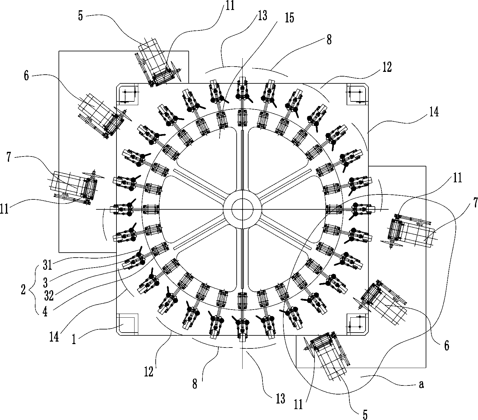
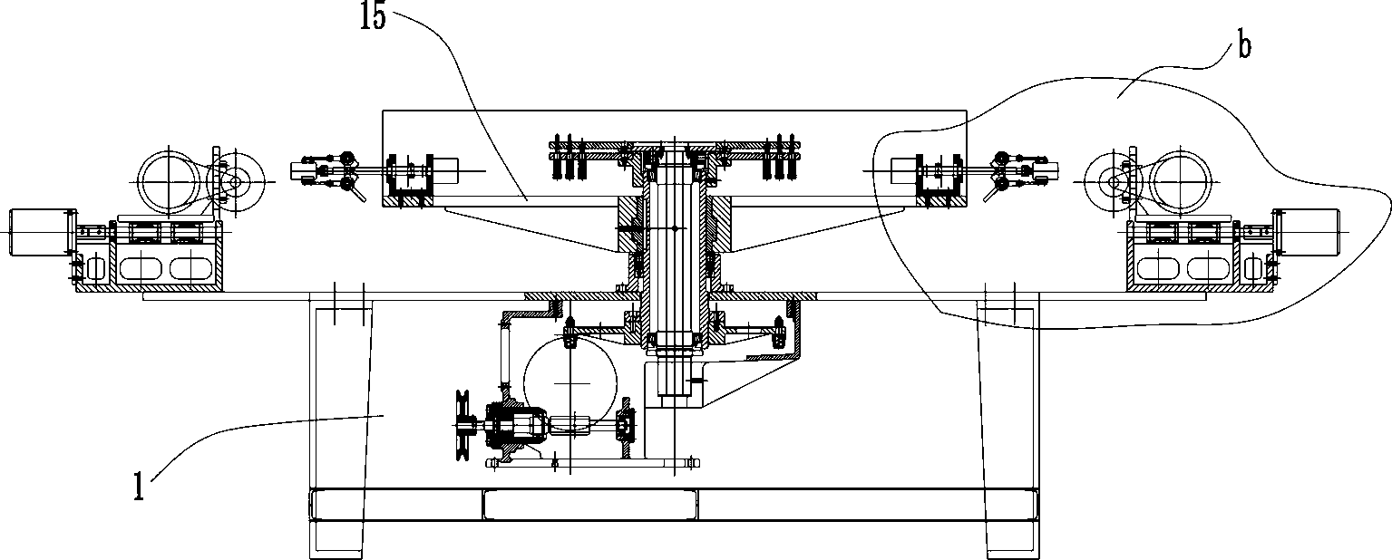
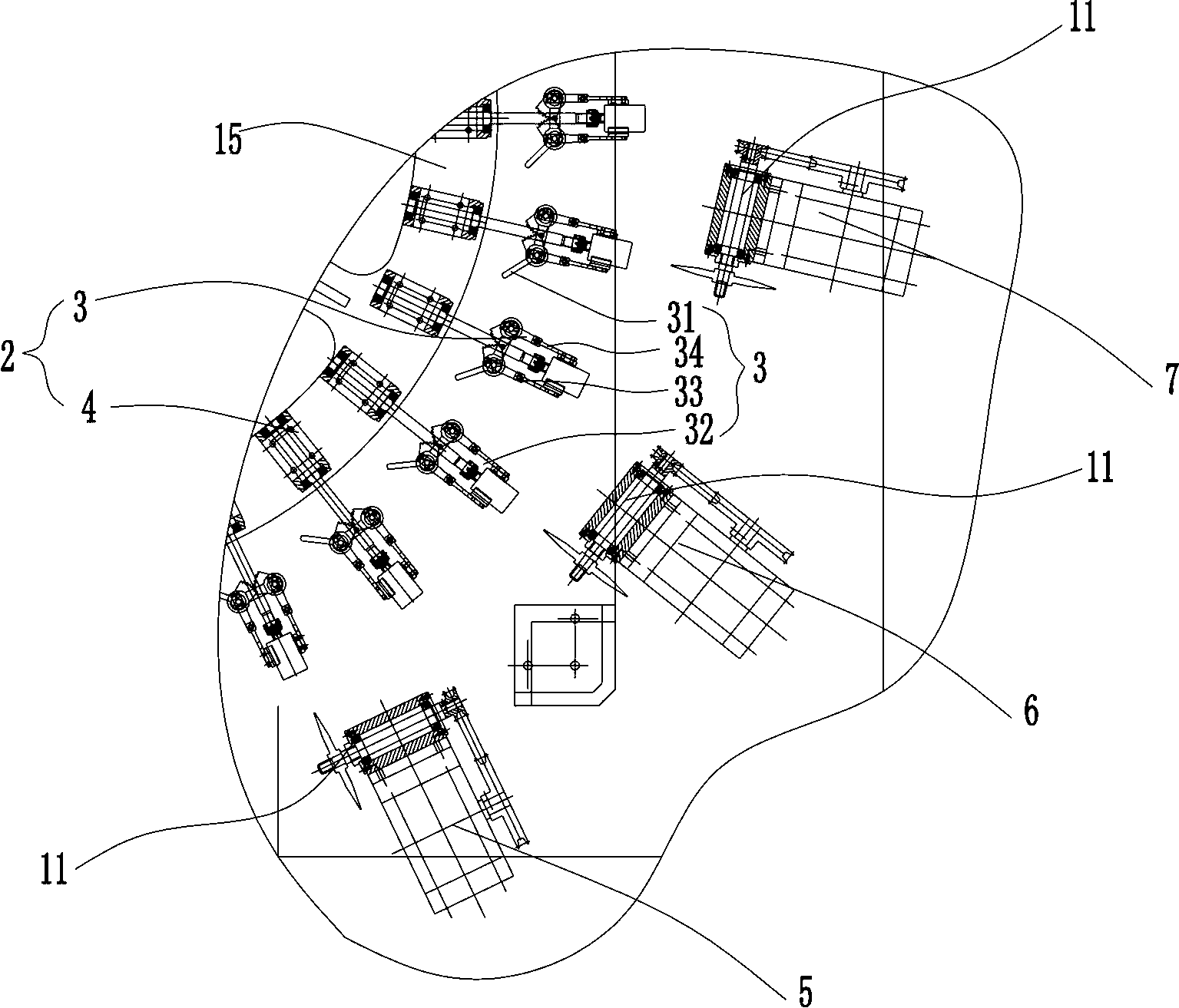
[0031] see Figure 1-5 , this implementation case includes: a multi-station body 1, the body 1 is provided with a number of station heads 2 that run intermittently on the stations, and the station head 2 is provided with a fixture 3 and a fixture 3 for fixing the full spiral lamp tube 9 The steering device 4 and the control device for controlling the steering angle of the steering device 4, coordinating the steering angle of the steering device 4, and the intermittent movement of the station head. On the bit head 2, the steering device 4 of the clamp 3 is a stepper motor 41 connected to the clamp 3 or an angle actuator or a mechanical device such as a gear and a shift fork that cooperate with each other. In this embodiment, it is a stepper motor; wherein the steering device 4 It is provided with an angler that feeds back the steering angle of the fixture 4 to the PLC control device. The steering device, angle detector, and PLC control device form a closed loop, which has achie...


PUM


Abstract

The invention discloses a full spiral lamp tube cutter and a full spiral lamp tube cutting process. The full spiral lamp tube cutter comprises a multi-station machine, wherein the machine is provided with a plurality of station heads which are intermittently operated on the stations, and each station head is provided with a clamp for fixing and positioning a full spiral lamp tube. The invention is characterized in that the clamp is rotatably arranged on the station head by using the axial line of the full spiral lamp tube as the rotation axis; the station head is provided with a clamp rotating device and a control device for controlling the rotation angle of the rotating device and coordinating the rotation angle of the rotating device and the intermittent movement of the station head; and at least one group of a workpiece chucking station, a coarse cutting station, a first fine cutting stations, a second fine cutting station and a tube lowering station are sequentially arranged in the station head operating direction, and the coarse cutting station, the first fine cutting stations and the second fine cutting station are used for cutting pins. By arranging the clamp rotating device, the coarse cutting station, the two fine cutting stations for cutting pins and the control device for coordinating the operation of all the components on the machine, the invention can automatically and accurately cut the pins of the full spiral lamp.

Description

technical field [0001] The invention relates to a full spiral lamp tube cutting machine, especially a cutting machine capable of precisely cutting pipe pins, and a cutting process using the machine. Background technique [0002] The cutting of full spiral lamp pins is mainly made by hand at present; the operator directly takes out the red-hot glass tube from the heating furnace and puts it on a special fixture to cut off, or the operator uses a cutting wheel to cut off the excess part of the lamp tube pins , this way is labor-intensive, the work efficiency is low, and the cutting quality is difficult to guarantee, which inevitably affects the honest process. [0003] In order to solve the above problems, ZL200820085205.4 discloses an automatic pin cutting machine, but this tube cutting machine is limited to roughly cutting off the pins of the half-spiral lamp tube, and cannot cut off the pins of the full spiral lamp tube. The requirements for the pins of the full spiral lam...

Claims


Application Information

Patent Timeline
Patent Type & Authority Patents(China)
IPC IPC(8): C03B33/06
Inventor 宣永昌
Owner HANGZHOU YONGCHANG GLASS MACHINERY
Learn More