Box foaming rocking mechanism

A technology of swing mechanism and link mechanism, which is applied in the field of box foam swing mechanism, can solve problems such as long debugging time, swing core-pulling block with gallbladder, and increased load of foaming equipment, so as to reduce material and processing costs and improve mechanism Lightweight and flexible, the effect of improving product quality

Inactive Publication Date: 2011-07-20
滁州市博精模具设备制造有限公司
View PDF3 Cites 2 Cited by
  • Summary
  • Abstract
  • Description
  • Claims
  • Application Information

AI Technical Summary

Problems solved by technology

The disadvantages of this swing mechanism are: (1) The power of this mechanism comes from the side plate of the fixture, which drives the movement of the table rod, and then drives the movement of the swing core block, and the linkage construction is complicated; although the rising speed of the fixture is the same as the foaming box enters The speed of the mold core is consistent (the movement of the fixture directly drives the movement of the pre-foaming box), but the movement of the pre-foaming box is inconsistent with the movement of the swinging core-pulling block, so that there will be a belt of swinging core-pulling block gallbladder phenomenon; the splicing gap between the inner tank and the side plate after foaming is large, which affects the product quality and seriously leads to the scrapping of the product; (2) There are many structural parts in this mechanism, and it is prone to failure during use; ( 3) In the production process of this mechanism, the debugging time is long, the debugging is difficult, and the quality stability is poor in the product production process; (4), the structural parts of this mechanism are many, resulting in increased costs and waste of resources; (5), this The power of the mechanism comes from the side plate of the fixture, and the load on the foaming equipment increases, resulting in energy consumption and uneconomical

Method used


Image

  • Box foaming rocking mechanism
  • Box foaming rocking mechanism
  • Box foaming rocking mechanism

Examples


Embodiment Construction

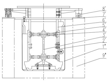
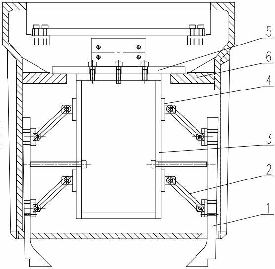
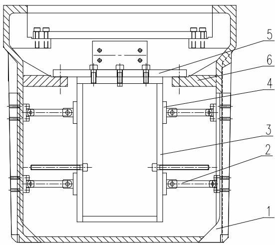
[0018] Such as figure 2 , image 3 As shown, the box foaming oscillating mechanism of the present invention includes a oscillating core pulling block 1, a connecting rod mechanism and a fixing frame 3 for fixing the connecting rod mechanism. The connecting rod mechanism includes a connecting rod 2 and a connecting rod seat 4, and the connecting rod One end of the connecting rod seat is movably connected with the connecting rod seat through a pin shaft, and the connecting rod seat is fixed on the fixed frame. The rod can move in a vertical plane; the fixed frame is a rectangular frame structure, and its upper end surface is fixed on the connecting plate 5 of the fixed frame, and the connecting plate of the fixed frame is fixed on the core body 6; the connecting rod is movably connected to the end faces of both sides of the rectangular holder.

[0019] The working principle of the box foaming swing mechanism of the present invention: when the foamed pre-packed box is placed i...


PUM


Abstract

The invention discloses a box foaming rocking mechanism, which comprises a rocking core-pulling block, a connecting rod mechanism and a fixing frame used for fixing the connecting rod mechanism, wherein the connecting rod mechanism comprises a connecting rod; one end of the connecting rod is connected to the fixing frame; and the rocking core-pulling block is directly connected with the other end of the connecting rod movably. The power of the box foaming rocking mechanism is from a liner of a prefabricated box, the motion of the prefabricated box directly drives the rocking core-pulling block to move, and the lifting speed of a fixture is consistent with the speed that the liner enters or is separated from a mould core; therefore, a phenomenon that the rocking core-pulling block drives the liner is avoided and the product quality is greatly improved.

Description

[0001] technical field [0002] The invention relates to a box foaming swing mechanism. Background technique [0003] When manufacturing foam molds for refrigerator boxes, the mold core generally needs to have a demoulding mechanism when foaming. The swing mechanism used for foaming and demoulding is as follows: figure 1 As shown, it mainly drives the linkage of a series of workpieces connected to it through the upward movement of the fixture, and then adjusts the swinging core-pulling block and the pre-installed box to a suitable foaming position. The working principle is roughly as follows: when After the foamed pre-packed box is placed in the fixture, the fixture starts to rise, and the friction plate 7' above the side plate 9' of the fixture is driven to rise with the roller 8', and at the same time, it drives the table rod 6' to rise, and the table rod 6' rises again. Drive the connecting plate 2', and finally the connecting plate 2' drives the swing core-pulling ...

Claims


Application Information

Patent Timeline
Patent Type & Authority Applications(China)
IPC IPC(8): B29C44/34
Inventor 张玉宏程曦王彦桥梅骏许杨
Owner 滁州市博精模具设备制造有限公司
Why Eureka
Try Eureka