Straw raking machine

A technology for harvesting machines and straws, which is applied in the direction of harvesters, etc., to achieve the effects of simple structure, improved recycling level, and easy popularization and application

Inactive Publication Date: 2013-10-02
孙明芹
View PDF6 Cites 0 Cited by
  • Summary
  • Abstract
  • Description
  • Claims
  • Application Information

AI Technical Summary

Problems solved by technology

[0003] In order to overcome the deficiencies of the existing straw collection machinery, the present invention provides a straw collecting machine, which is suitable for supporting large, medium and small wheeled tractors.

Method used


Image

  • Straw raking machine
  • Straw raking machine

Examples


Embodiment Construction

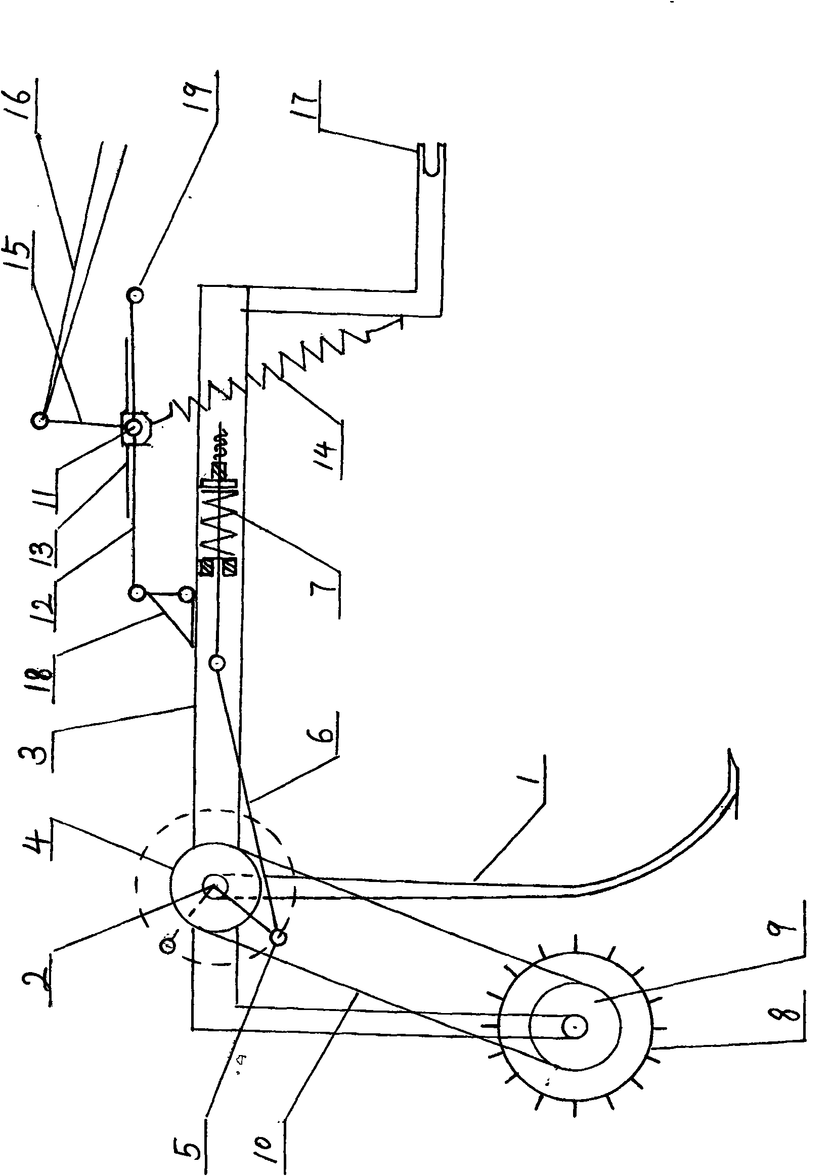
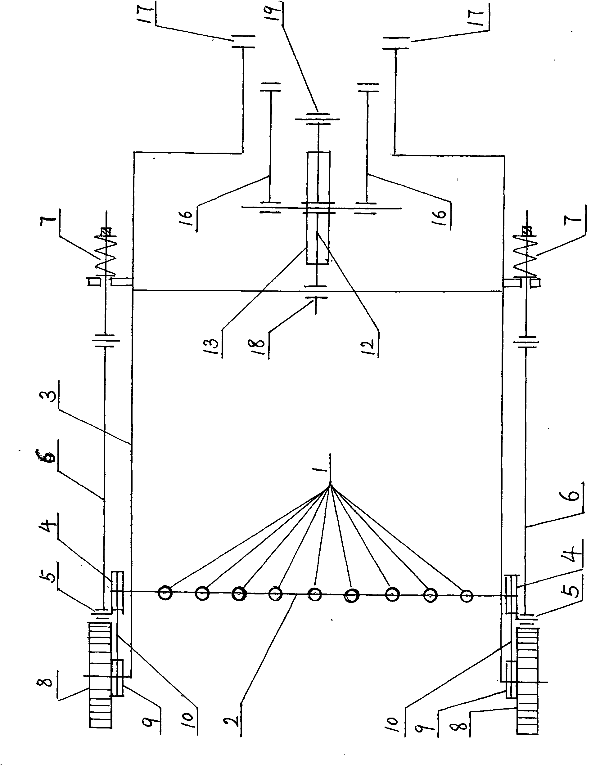
[0018] exist figure 1 figure 2 In the embodiment of the present invention, a plurality of shank pillars 1 bent backward into an arc are arranged horizontally and spaced on the shank 2, the shank 2 is installed on the frame 3, and sprockets are installed on both ends of the shank 2. 4 and the rocker arm 5, the connecting rod 6 is installed on the rocker arm 5, and the compression spring 7 is installed on the other end of the connecting rod 6, and the shaft 2 can turn backward 360 degrees under the action of the rocker arm 5 and the upper sprocket 4 , the barbed ground wheel 8 and the lower sprocket 9 are installed below the frame 3, and the upper sprocket 4 is driven by the chain 10 to rotate. Mount the push rod 12 connected with the shaft pin 11 and the push rod pressing plate 13, and can bend upwards with the shaft pin 11 as the inflection point. The pull-down spring 14 is installed under the shaft pin 11, and the orientation triangle 18 is installed on the frame 3. The low...


PUM


Abstract

The invention relates to a straw raking machine which is formed by transversely installing multiple rake pillars on a rake shaft at intervals, wherein the rake shaft is installed on a rack; two clamp heads on the rack are connected with two traction pillars of a tractor; an ejector rob joint is connected to the tractor in a suspension mode; and a lifting rod is connected with the lifting arm of the tractor. Straw is collected into a stack through the traction of the tractor.

Description

technical field [0001] The invention relates to an agricultural machine, in particular to the technology of a straw collecting machine. Background technique [0002] In the prior art, there are round straw baler and square straw baler, but the structure is complicated, the price is high, the efficiency is low, and it is not easy to popularize and apply. Contents of the invention [0003] In order to overcome the shortcomings of the existing straw collecting machines, the invention provides a straw collecting machine, which is suitable for matching use with large, medium and small wheeled tractors. [0004] The technical solution adopted by the present invention to solve the technical problem is: install the straw collector behind the tractor, arrange a plurality of shafts (1) horizontally and at intervals on the shaft (2), and place the shaft (2) Installed on the frame (3). [0005] Said many pillars (1) all bend backwards into an arc shape. [0006] Sprockets (4) and r...

Claims


Application Information

Patent Timeline
Patent Type & Authority Patents(China)
IPC IPC(8): A01D85/00
Inventor 孙明芹
Owner 孙明芹
Why Eureka
Try Eureka