
Recorder/reproducer

A reproduction device and recording unit technology, applied in the direction of digital recording/reproduction, data recording, recording signal processing, etc., can solve the problem that the reproduction track cannot be specified

Inactive Publication Date: 2011-07-13
YAMAHA CORP
View PDF12 Cites 9 Cited by
  • Summary
  • Abstract
  • Description
  • Claims
  • Application Information

AI Technical Summary

Problems solved by technology

[0010] The problem to be solved is that the operator (or user) of the recording / reproducing device cannot intuitively specify the reproduction track (or reproduction channel) according to the seat positions of the attendees in the meeting

Method used


Image

  • Recorder/reproducer
  • Recorder/reproducer
  • Recorder/reproducer

Examples


Embodiment 1

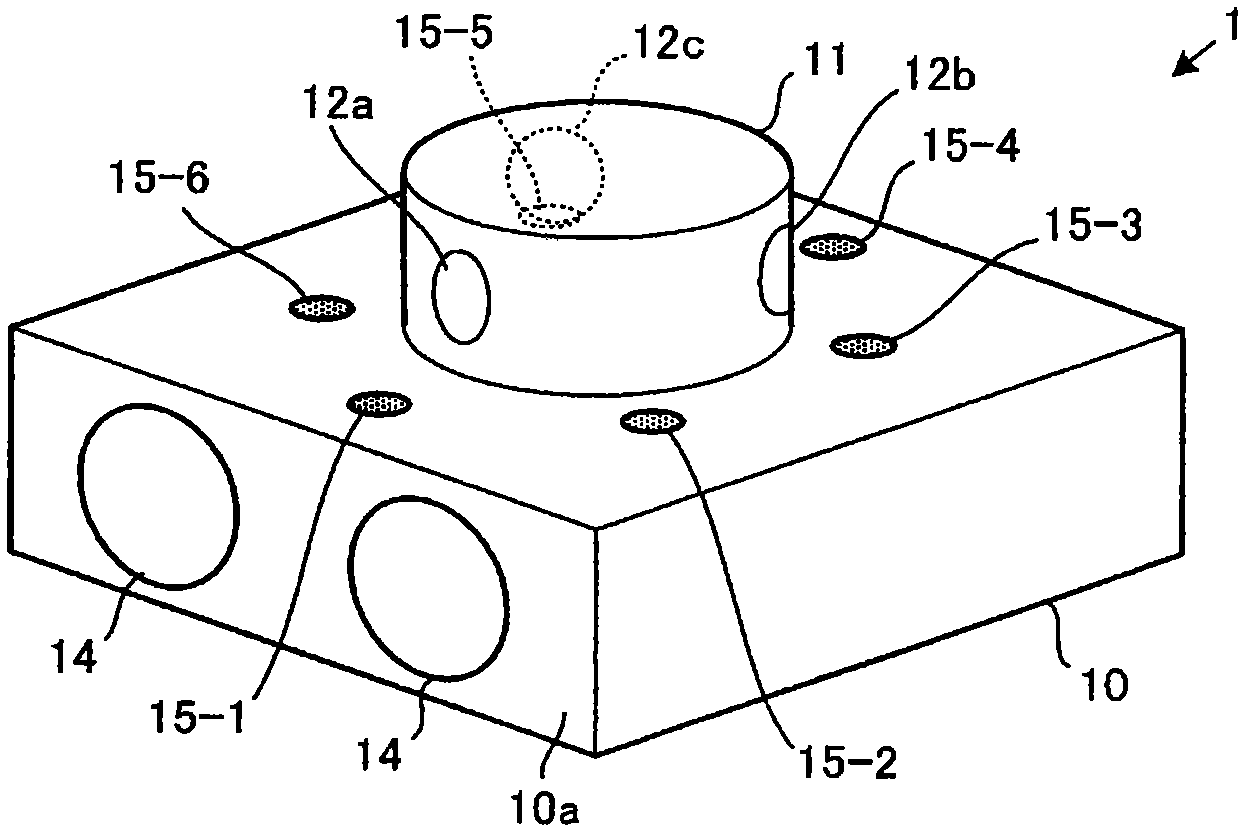
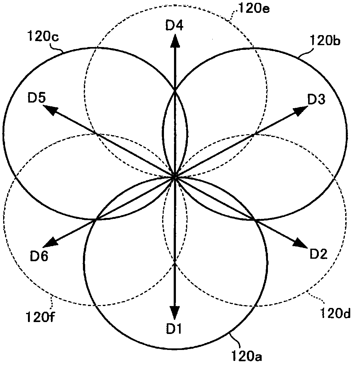
[0048] figure 1 is a perspective view showing the appearance of the recording / reproducing apparatus according to Embodiment 1 of the present invention. figure 2 is a schematic diagram showing the directivity characteristics of the microphones 12 (12a, 12b, 12c) installed in the recording / reproducing apparatus 1.

[0049] The recording / reproducing device 1 has a low-height cuboid-shaped housing 10 in which a cylindrical sound collector 11 is disposed centrally on the upper surface of the housing 10 . A speaker 14 is arranged on one side 10 a among four sides of the housing 10 . In the following description, the direction in which the side face 10 a of the speaker 14 is arranged will be referred to as a front direction.

[0050] Three microphones 12a, 12b, 12c are attached to the side of the sound collector 11 with an angular interval of 120 degrees therebetween. Specifically, the microphone 12a is arranged in the forward direction of the sound collector 11; the microphone 1...

Embodiment 2

[0075] Next, the recording / reproducing device 2 according to Embodiment 2 of the present invention will be described in detail. Figure 8 and Figure 9 is a perspective view showing the appearance of the recording / reproducing device 2 of Embodiment 2. In the recording / reproducing device 2, opening / closing adjustable arms 51, 52 are attached to opposite sides of a housing 50 having a triangular prism shape. Figure 8 An open state in which the arms 51, 52 of the recording / reproducing device 2 are opened is shown; Figure 9 A closed state in which the arms 51, 52 of the recording / reproducing device 2 are closed is shown.

[0076] A unidirectional microphone 55 - 1 is attached to the front side 50 a of the three sides of the case 50 . In addition, a direction indicator switch 56 - 1 for specifying the direction of the microphone 55 - 1 and a speaker 53 are arranged on the upper surface of the housing 50 .

[0077] Arms 51, 52 are rotationally adjustable attached to opposite s...


PUM


Abstract

A recorder / reproducer comprises a plurality of unidirectional microphones and a plurality of direction designation switches. The unidirectional microphones are arranged at a predetermined angular interval for the circumference, and the direction designation switch can designate a direction other than a plurality of directions concretely provided by the unidirectional microphones. In a normal reproduction state, a plurality of voice signals collected by the unidirectional microphones and recorded are read out in parallel and reproduced. When any one direction designation switch is operated, only a voice signal corresponding to a designated direction is read out selectively and reproduced. When a direction other than the plurality of directions concretely provided by the unidirectional microphones is designated, a voice signal collected by two unidirectional microphones arranged across a designated direction is read out selectively and reproduced.

Description

technical field [0001] The present invention relates to a recording / reproducing device that collects sounds in multiple directions uttered by multiple conference participants to record and / or reproduce the sounds. [0002] This application claims priority from Japanese Patent Application No. 2008-213668 filed in Japan on August 22, 2008 and Japanese Patent Application Publication No. 2009-191242 filed in Japan on August 20, 2009, the contents of which are incorporated by reference combined here. Background technique [0003] Generally, sounds produced by a plurality of conference participants are recorded, and then the recorded content is confirmed when the sounds are reproduced; therefore, various recording / reproducing devices and techniques like Patent Document 1 have been developed. When a plurality of attendees participating in a meeting speak at their positions, a plurality of microphones are used to pick up a plurality of sounds, and they are recorded in a multi-track...

Claims


Application Information

Patent Timeline
Patent Type & Authority Applications(China)
IPC IPC(8): H04R3/00G11B20/10H04R1/40
CPCG11B20/10527G11B27/034H04R1/406G11B2020/10601H04R3/005G11B27/105
Inventor 畑纪行小林咏子
Owner YAMAHA CORP
Learn More