Precise motion driving device based on bionics principle

A driving device and precision motion technology, which is applied in the field of geometric measurement, can solve the problems of inability to realize large-scale high-precision scanning, inability to realize ultra-fine and smooth motion in the range of motion, and difficulty in combination, and achieve simple structure and high motion resolution , the effect of a large range of motion

Inactive Publication Date: 2011-07-13
BEIJING CHANGCHENG INST OF METROLOGY & MEASUREMENT AVIATION IND CORP OF CHINA
View PDF3 Cites 5 Cited by
  • Summary
  • Abstract
  • Description
  • Claims
  • Application Information

AI Technical Summary

Problems solved by technology

[0002] In the field of geometric quantity measurement technology, the more commonly used precision motion and positioning devices usually use the drive mode of motor plus screw, which can realize a wide range of motion, but can only achieve micron-level motion resolution; Piezoelectric ceramic micro-displacement driver mode, this driving method can achieve nanoscale motion resolution, but the motion range is usually only micron level; to achieve nanoscale motion resolution and positioning accuracy in a large motion range, only coarse motion and The two-stage motion method combined with micro-movement uses a motor plus a screw to achieve a large range of motion, and then uses a piezoelectric ceramic micro-displacement drive device to achieve a small range of adjustment. The disadvantage of this method is that the combination of the two drive methods is very difficult , can not achieve ultra-fine and smooth movement of the entire range of motion, especially can not achieve a wide range of high-precision scanning

Method used


Image

  • Precise motion driving device based on bionics principle
  • Precise motion driving device based on bionics principle
  • Precise motion driving device based on bionics principle

Examples


Embodiment

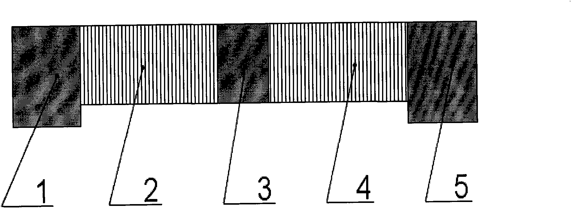
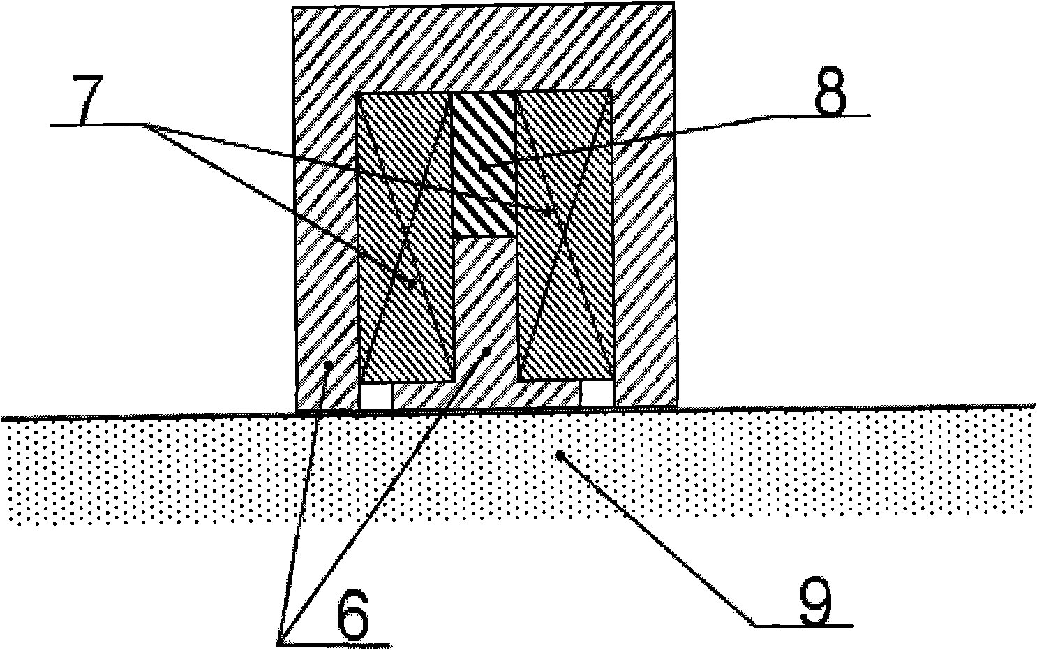
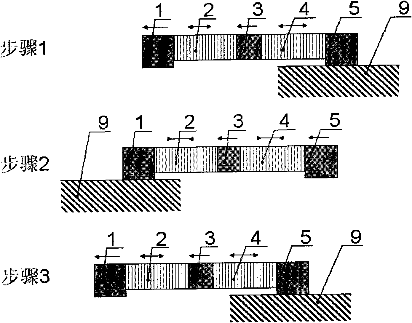
[0034] A precision motion drive device based on the principle of bionics, such as figure 1 As shown, it consists of a front suction cup, a front piezoelectric ceramic micro-displacement drive element, a motion output fulcrum, a rear piezoelectric ceramic micro-displacement drive element, and a rear suction cup, and its peripheral equipment is an iron soft magnetic magnetic plate for a fixed drive device;

[0035] The front suction cup, the front piezoelectric ceramic micro-displacement drive element, the motion output fulcrum, the rear piezoelectric ceramic micro-displacement drive element, and the rear suction cup are arranged in a straight line, and the front piezoelectric ceramic micro-displacement drive element and the rear piezoelectric ceramic micro-displacement drive element The direction of motion is also on this straight line;

[0036] One end of the front piezoelectric ceramic micro-displacement drive element and one end of the rear piezoelectric ceramic micro-displa...


PUM


Abstract

The invention relates to a precise motion driving device based on a bionics principle and belongs to the technical field of geometric quantity measurement. The precise motion driving device comprises a front sucker, a front piezoelectric ceramics micrometric displacement driving element, a motion output supporting point, a back piezoelectric ceramics micrometric displacement driving element, and a back sucker, wherein an iron soft magnetic conductive panel used for fixing the driving device is used as the peripheral equipment of the driving device; and the motion output supporting point is driven to realize the nanometer precise positioning driving in a large motion scope by coordinating the suction actions of the front and back suckers and the stretching actions of the front and back piezoelectric ceramics micrometric displacement driving elements and pushing. The precise motion driving device based on a bionics principle has simple structure, low heat productivity, no pause in motion process, high motion resolution ratio and large motion scope which is only limited by the size of the iron soft magnetic conductive panel. The precise motion driving device can realize the precise motion and is suitable for the occasions requiring low-speed running.

Description

technical field [0001] The invention relates to a precision motion drive device based on the bionic principle, which belongs to the technical field of geometric quantity measurement. Background technique [0002] In the field of geometric quantity measurement technology, the more commonly used precision motion and positioning devices usually use the drive mode of motor plus screw, which can realize a wide range of motion, but can only achieve micron-level motion resolution; Piezoelectric ceramic micro-displacement driver mode, this driving method can achieve nanoscale motion resolution, but the motion range is usually only micron level; to achieve nanoscale motion resolution and positioning accuracy in a large motion range, only coarse motion and The two-stage motion method combined with micro-movement uses a motor plus a screw to achieve a large range of motion, and then uses a piezoelectric ceramic micro-displacement drive device to achieve a small range of adjustment. The...

Claims


Application Information

Patent Timeline
Patent Type & Authority Applications(China)
IPC IPC(8): H02N2/02
Inventor 李华丰朱振宇王霁李强兰一兵
Owner BEIJING CHANGCHENG INST OF METROLOGY & MEASUREMENT AVIATION IND CORP OF CHINA
Why Eureka
Try Eureka