
Combing device for combing fibrous material

A fiber material and combing technology, which is applied in the direction of combing machines, fiber processing, textiles and papermaking, etc., can solve the problems of increased noise, high vibration of loading device, and limitation of pressure load adjustability, etc., to reduce noise level and vibration Effect

Inactive Publication Date: 2012-03-21
MASCHINENFABRIK RIETER AG
View PDF3 Cites 0 Cited by
  • Summary
  • Abstract
  • Description
  • Claims
  • Application Information

AI Technical Summary

Problems solved by technology

This also produces very high vibrations of the loading device and increases the generation of noise
Furthermore, existing solutions are limited in the adjustability of the pressure load

Method used


Image

  • Combing device for combing fibrous material
  • Combing device for combing fibrous material
  • Combing device for combing fibrous material

Examples


Embodiment Construction

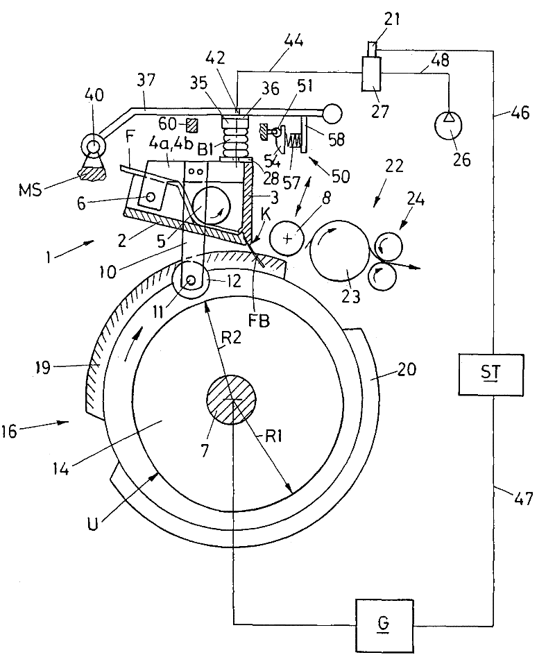
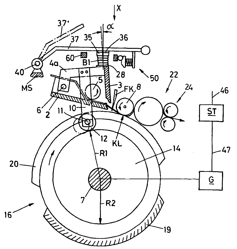
[0030] exist figure 1 A schematic diagram of a combing head of a combing machine is shown in . Usually a large number (for example eight) of such combing heads are arranged next to each other and are drive-connected to one another via continuous drive elements (longitudinal shafts). However, it is also possible to equip the combing heads each with a single drive.

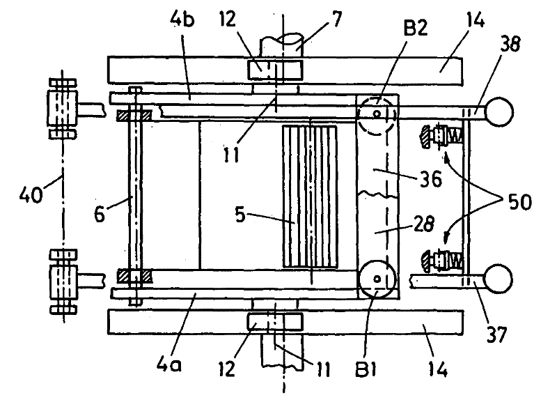
[0031] A nipper unit 1 (referred to as nipper 1 ) is arranged above the combing cylinder 16 connected to the driven shaft 7 , and the nipper unit is provided with a lower nipper 2 and an upper nipper 3 . The upper nipper 3 is connected to the lateral arms 4a, 4b (see also image 3 ), the arm is swingably supported on the lower nipper around the swing axis 6 . Since the lower nipper 2 assumes a stationary position in the present exemplary embodiment (that is, it cannot move during the combing cycle), the pivot axis 6 can also be accommodated directly in the frame MS. On the arms 4a, 4b are each fastened a clip 10...


PUM


Abstract

The invention relates to a combing device for combing a fibrous material (F) which is supplied to a clamping assembly (1) that is supported in a machine frame (MS) and has a lower and upper clamping plate (2, 3), wherein the upper clamping plate (3) is movably supported with respect to the lower clamping plate (2) so as to form a clamping point (KS) and is pressurized by a loading unit (B1, B2) so as to produce a clamping force, and furthermore is provided with a feeding means (5) for intermittently supplying the fibrous material (F) to the clamping point (KS) of the clamping assembly, with which beneath thereof a combing cylinder (16) is associated that is rotatably supported in the machine frame (MS) and provided with at least one combing segment (19) on the periphery thereof, and wherein said plate is also provided with a tear-off means (8) associated with the clamping assembly. In order to obtain an improved loading device for the upper clamping plate which compared to the known solution exhibits good damping properties and has a low noise level, according to the invention the loading device is composed of bellows cylinders (B1, B2) which are pressurized with compressed air byway of a compressed air source (26) and which, with one end (35) thereof, are directly or indirectly supported on the machine frame (MS) and which, with the other end (30) thereof, are supported by elements (4a, 4b, 28) connected to the upper clamping plate (3).

Description

technical field [0001] The invention relates to a combing device for combing fibrous material, which is fed into a nipper unit supported in a machine frame, said nipper unit having a lower nipper and an upper nipper, wherein for forming The jaws movably support the upper nipper with respect to the lower nipper, and the upper nipper is loaded by a loading device in order to generate a clamping force, and the nipper unit has a feeding mechanism for intermittently feeding fiber material into the nipper the jaws of the trigger unit, for which the nipper unit is provided below with a combing cylinder rotatably supported in a frame, the combing cylinder being provided with at least one combing segment on its circumference, and It has a separation mechanism attached to the nipper unit. Background technique [0002] In today's conventional combing machines an oscillating nipper unit is used which is arranged above a rotating combing cylinder (also called a "circular comb") and whic...

Claims


Application Information

Patent Timeline
Patent Type & Authority Patents(China)
IPC IPC(8): D01G19/16D01G19/10
CPCD01G19/10D01G19/16
Inventor U·斯图茨W·斯拉维克D·索默
Owner MASCHINENFABRIK RIETER AG
Learn More