
Effective image area detection method and system

A detection method and effective area technology, which are applied in the field of image effective area detection methods and systems, and can solve the problems of different display positions and the existence of black borders in images.

Inactive Publication Date: 2011-06-29
GUANGDONG VTRON TECH CO LTD
View PDF5 Cites 15 Cited by
  • Summary
  • Abstract
  • Description
  • Claims
  • Application Information

AI Technical Summary

Problems solved by technology

For the various signal source devices on the market (such as computer graphics card and DVD, etc.), there is no unique standard to specify the area of ​​effective analog image signals at various resolutions, so different analog signal sources can be displayed on the same display terminal. When displaying, the display position of the image may be different. The most obvious manifestation is that there are black borders around the image.

Method used


Image

  • Effective image area detection method and system
  • Effective image area detection method and system
  • Effective image area detection method and system

Examples


Embodiment Construction

[0074] The present invention will be further described below in conjunction with the accompanying drawings.

[0075] The starting coordinates are the smallest row coordinates and column coordinates among all effective pixels;

[0076] Calculate the length and width of the effective display area according to the resolution of the image;

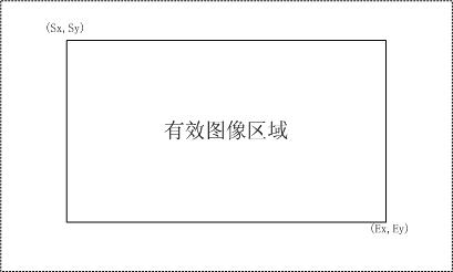
[0077] Calculate the end coordinates of the effective display area according to the starting row and column coordinates and the length and width of the effective display area. The effective area of ​​the image is as image 3 shown.

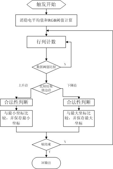
[0078] The method process of the embodiment of the present invention is as figure 1 As shown, in the embodiment, the image color parameter is an RGB value, and the effective threshold of color is an effective threshold of RGB, comprising the following steps:

[0079] For each image frame, do the following:

[0080] Step 1, calculate image RGB effective threshold;

[0081] 1) First calculate the average val...


PUM


Abstract

The invention discloses an effective image area detection method and an effective image area detection system. By the method and the system, the aims of automatically identifying the effective area of an analogue signal and regulating an optimal display position are fulfilled, and the problem of blackedging in the display of the analogue image signal is effectively solved. The method comprises the following steps of: detecting whether image data corresponding to each pixel clock belongs to an effective image or not, and recording coordinate values of the image data; taking counted minimum row and column coordinates as starting coordinates of the effective image area, and taking counted maximum row and column coordinates as the ending coordinates of the effective image area; and finally making a range judgment on a detection result, and outputting an effective signal if a range is legal.

Description

technical field [0001] The invention relates to the field of image display, in particular to a method and system for detecting an effective area of ​​an image. technical background [0002] At present, the transmission and restoration of analog image signals (ARGB and CVBS, etc.) do not have an effective image indication signal (DE), so when the display terminal displays the analog signal, it is based on a preset (empirical value) effective display area or by manually setting the effective display area. For the various signal source devices on the market (such as computer graphics card and DVD, etc.), there is no unique standard to specify the area of ​​effective analog image signals at various resolutions, so different analog signal sources can be displayed on the same display terminal. When displaying, the display position of the image may be different. The most obvious manifestation is that there are black borders around the image. Contents of the invention [0003] T...

Claims


Application Information

Patent Timeline
IPC IPC(8): H04N17/00H04N17/02
Inventor 刘文军伍健庭贺文健
Owner GUANGDONG VTRON TECH CO LTD
Learn More