Method, system and device for detecting virtual link faults based on fiber channel over Ethernet (FCoE)

A fiber channel and detection method technology, applied in the field of FCoE virtual link failure detection, can solve problems such as affecting network bandwidth, and achieve the effect of rapid detection without wasting network bandwidth

Active Publication Date: 2013-06-26
NEW H3C TECH CO LTD
View PDF4 Cites 0 Cited by
  • Summary
  • Abstract
  • Description
  • Claims
  • Application Information

AI Technical Summary

Problems solved by technology

If the length of FKA_ADV_PERIOD is shortened, although the above problems can be solved, the shorter period will cause a large number of control packets to be transmitted in the network, which will affect the network bandwidth.

Method used


Image

  • Method, system and device for detecting virtual link faults based on fiber channel over Ethernet (FCoE)
  • Method, system and device for detecting virtual link faults based on fiber channel over Ethernet (FCoE)
  • Method, system and device for detecting virtual link faults based on fiber channel over Ethernet (FCoE)

Examples


Embodiment 1

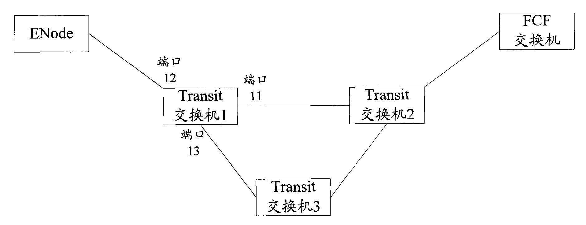
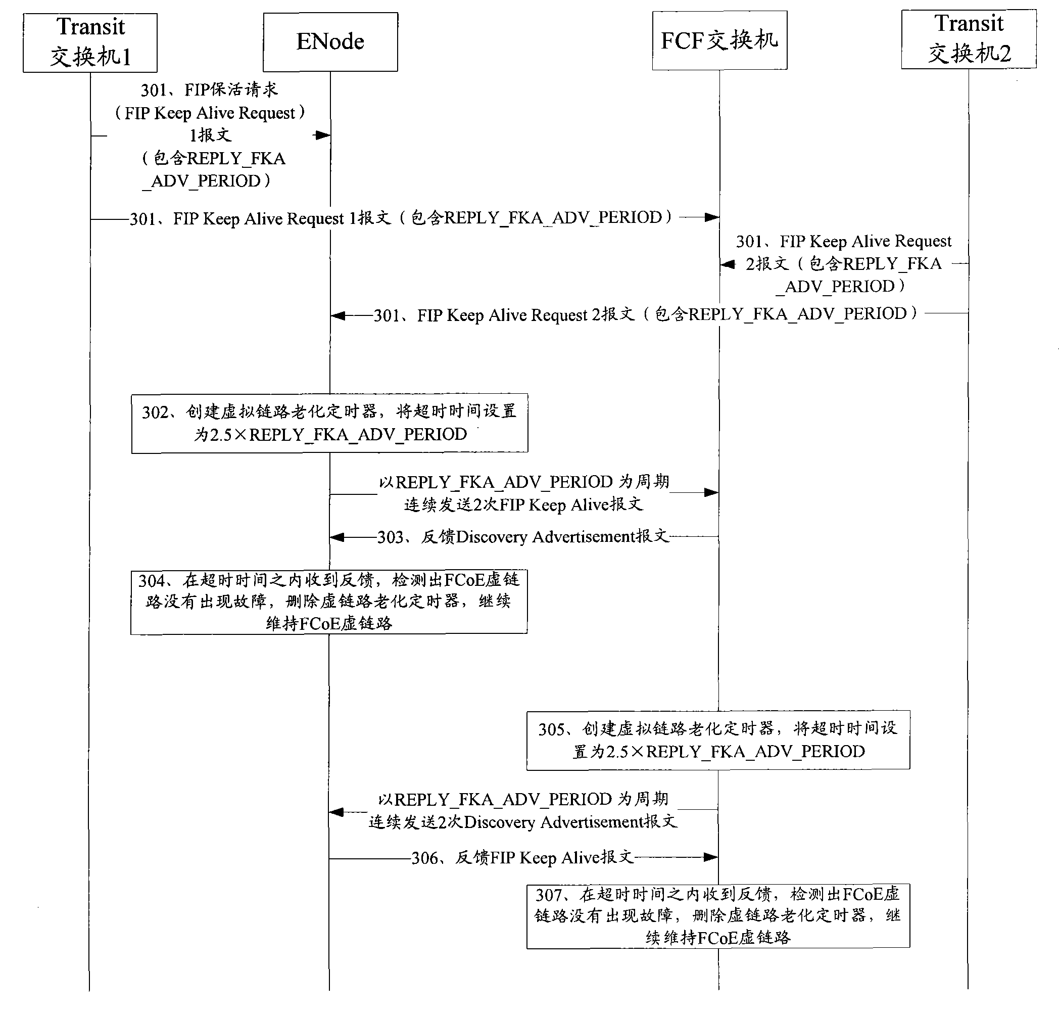
[0041] see image 3 , image 3 This is an implementation flow chart of Embodiment 1 of the method for detecting an FCoE virtual link fault according to the present invention. This embodiment is applied to figure 1 The FCoE network structure shown is taken as an example for illustration. Assuming that the network link between Transmit switch 1 and Transmit switch 2 is faulty, the detection method includes the following steps:

[0042] Step 301 : The network link between Transmit switch 1 and Transmit switch 2 is faulty. Transmit switch 1 and Transmit switch 2 find the fault, and both send a FIP Keep Alive Request message containing REPLY_FKA_ADV_PERIOD, and send the Transmit The message sent by switch 1 is recorded as a FIP Keep Alive Request 1 message, and the message sent by Transmit switch 2 is recorded as a FIP Keep Alive Request 2 message.

[0043] In this step, the REPLY_FKA_ADV_PERIOD in the FIP Keep Alive Request 1 message and the FIP Keep Alive Request 2 message are...

Embodiment 2

[0056] Figure 4 A schematic diagram of an FCoE network structure applied in Embodiment 2 of the present invention, Figure 4 The FCoE network includes Transmit switch 1 and Transmit switch 2.

[0057] see Figure 5 , Figure 5 This is an implementation flow chart of Embodiment 2 of the method for detecting an FCoE virtual link fault according to the present invention. Assuming that the network link between Transmit switch 1 and Transmit switch 2 is faulty, the detection method includes the following steps:

[0058] Step 501: The network link between Transmit switch 1 and Transmit switch 2 is faulty. Transmit switch 1 and Transmit switch 2 find the fault, and both send a FIP Keep Alive Request message containing REPLY_FKA_ADV_PERIOD (set to 100ms), and the Transmit switch The message sent by 1 is recorded as a FIP Keep Alive Request 1 message, and the message sent by Transmit switch 2 is recorded as a FIP Keep Alive Request 2 message.

[0059] In this step, the Transmit s...


PUM


Abstract

A failure detection method and device for a FCoE virtual link. A first FCoE devices receives a Keep Alive Request packet from a Transmit switch, the Keep Alive Request packet having a response period; in response to receiving the Keep Alive Request packet, the first FCoE device creates a virtual link aging timer, configures expiration time of the timer according to the response period, and transmits a packet for maintaining the FCoE virtual link to a second FCoE device. If the first FCoE device does not receive a packet for maintaining the FCoE virtual link returned by the second FCoE device by the time the timer expires, the first FCoE device detects that the FCoE virtual link between the first FCoE device and the second FCoE device is in failure.

Description

technical field [0001] The invention relates to the technical field of Fibre Channel over Ethernet (FCoE, Fibre Channel over Ethernet), in particular to a method, system and device for detecting FCoE virtual link failure. Background technique [0002] The FCoE protocol is a transport protocol that carries the FC protocol on the Ethernet. like figure 1 It is a schematic diagram of the FCoE network structure in the prior art. In the FCoE network, a device that supports the FCoE protocol is called an FCoE device, and a switch that supports the FCoE protocol is called an FCoE transmission (FCF, FCoE Forwarders) switch. The communication entity device is called an Ethernet node (ENode); in an FCoE network, an Ethernet switch that does not support the FCoE protocol but can transmit FCoE packets is called a transmission (Transmit) switch. exist figure 1 In the FCoE network shown, before the FCoE packets need to be exchanged between the FCF switch and the ENode, an FCoE virtual l...

Claims


Application Information

Patent Timeline
Patent Type & Authority Patents(China)
IPC IPC(8): H04L12/26H04L12/24H04L12/70H04L1/00
CPCH04L49/70H04L49/555H04L43/10H04L43/0811
Inventor 王晓东
Owner NEW H3C TECH CO LTD
Why Eureka
Try Eureka