Gas column structure for anti-vibration sleeve
A shock-proof sleeve, air column technology, applied in packaging and other directions, can solve problems such as inability to solve
Active Publication Date: 2011-06-29
KUNSHAN AIRBAG PACKING CORP
View PDF3 Cites 18 Cited by
- Summary
- Abstract
- Description
- Claims
- Application Information
AI Technical Summary
Problems solved by technology
The gas packaging bag is provided with a plurality of auxiliary gas columns to expand the gas-holding effect of the main gas column and improve the shock resistance of the gas packaging bag, so that the gas packaging bag with multiple auxiliary gas columns can withstand large impact loads; but The above-mentioned technology cannot solve the extrusion phenomenon of triangular bulges on the corners of the objects with a sharp and acute angle on the surface of the coated object and the air column after bending
Method used
View moreImage
Smart ImageViewing Examples
Examples
Embodiment Construction
Login to View More PUM
 Abstract
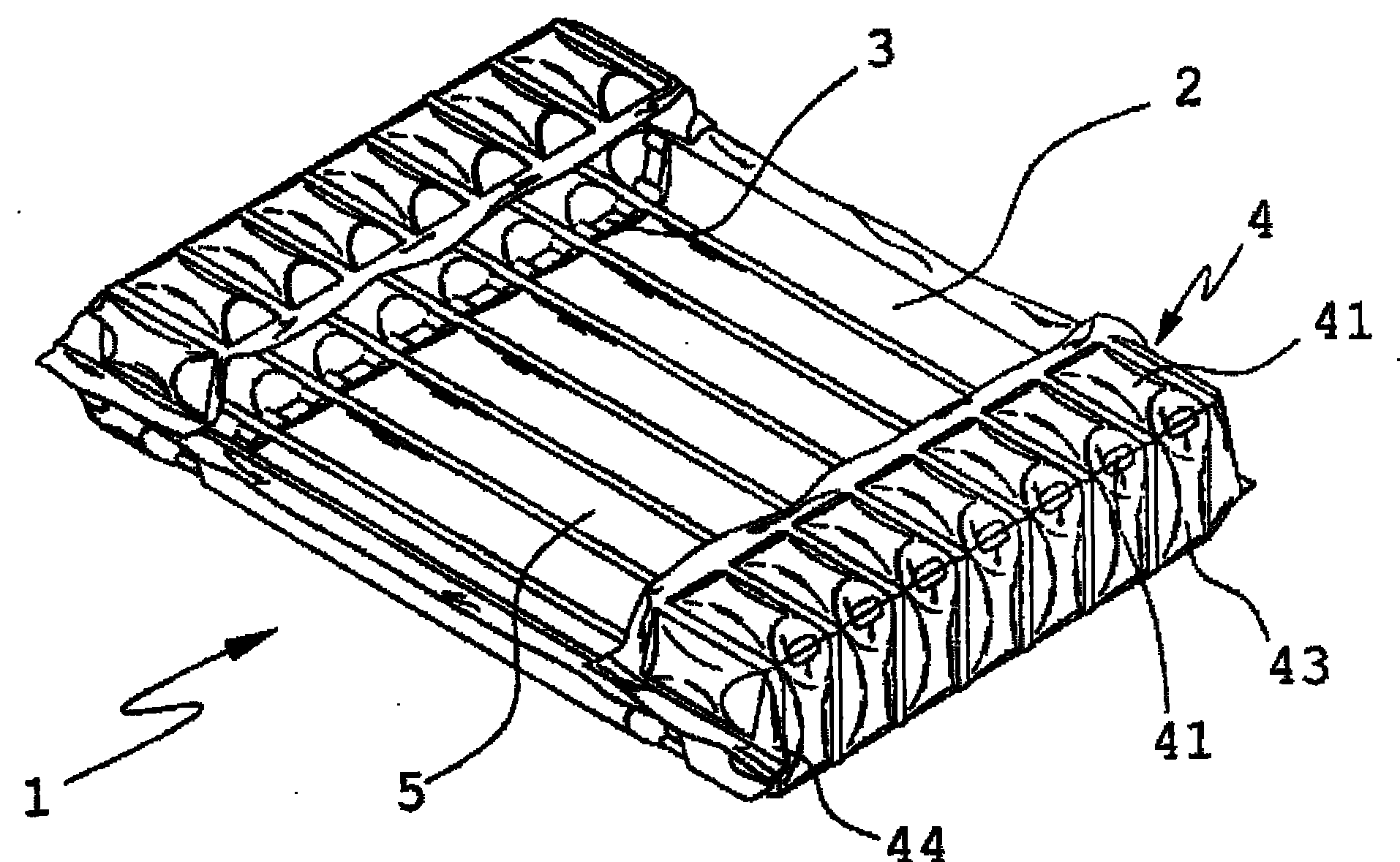
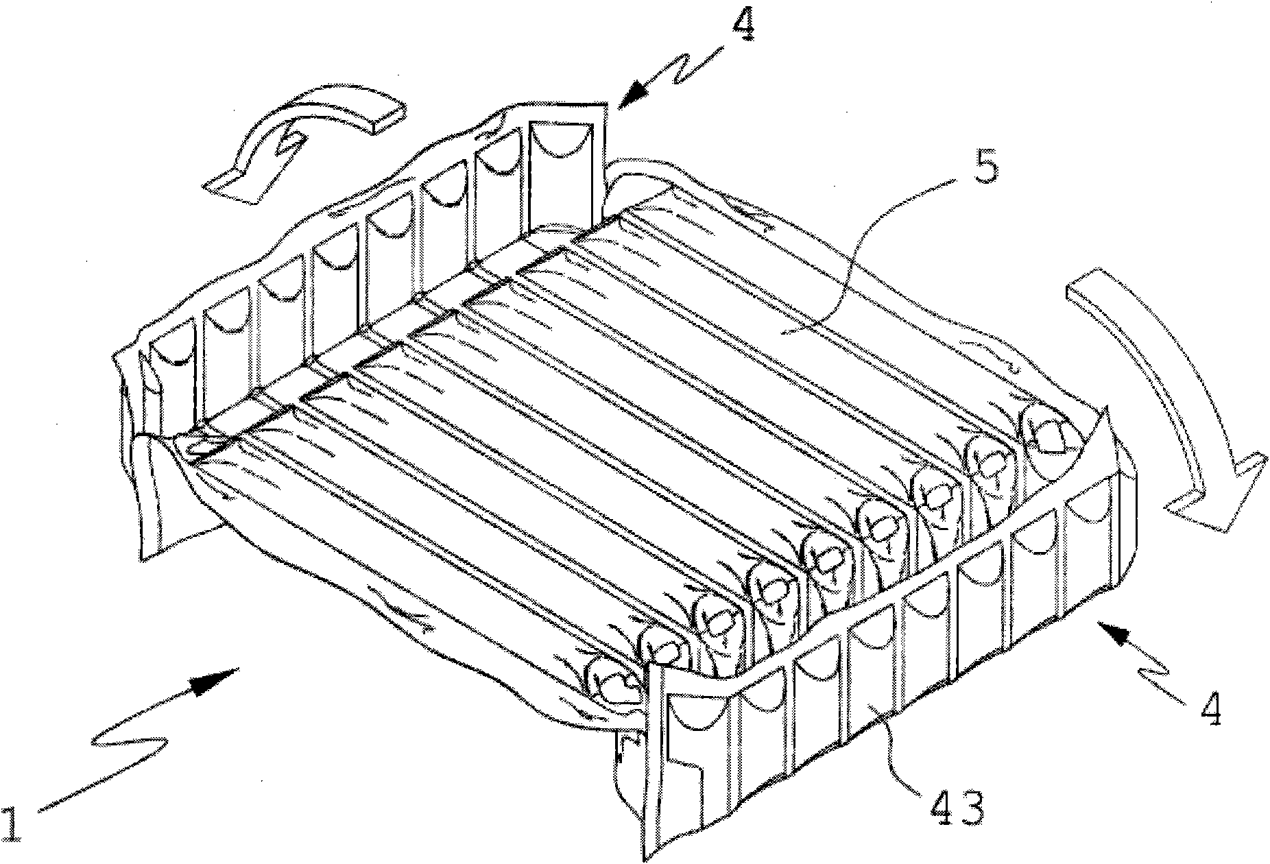
The invention discloses a gas column structure for an anti-vibration sleeve. The structure consists of a gas column plate, two bendable connecting wires and two concave buffer walls, wherein the concave buffer wall is formed by a plurality of U-shaped structures which are spliced by virtue of parallel heat seal; short gas columns in the center of the U-shaped structures at two ends of the concave buffer wall are not inflated, so that the four corners of the gas column structure of the anti-vibration sleeve cannot be cracked when contacting with a sharp object, and objects with sharp ends or of irregular shapes can be accommodated; and when the plurality of gas columns of the gas column plate are subjected to parallel heat seal, the heat seal can be performed at will to generate gas columns of irregular shapes. Furthermore, a dark curtain can be additionally arranged so as to achieve the effect of shielding the accommodating space, and serve as a movable curtain to cover and protect the semi-opening accommodating space.
Description
The air column structure of the shockproof sleeve technical field The invention relates to an air column structure, in particular to an air column structure of a shockproof sleeve. Background technique Shockproof cases are often used to cover and protect electronic products, such as projectors, DVDs, digital cameras, notebook computers, and mobile phones. Most of the early electronic products did not have display screens, and even if they had such screens, the area was relatively small. However, the screens of portable electronic products such as mobile phones and game consoles have been designed to become larger and larger. If the surface where the screen is placed is hit by a hard object, it is easy to cause damage to the screen, and then make the entire electronic product unusable; With the increase of portable electronic products, the corresponding shockproof case products also appear relatively, such as mobile phone cases, digital camera cases, notebook cases, etc. Th...
Claims
Login to View More Application Information
Patent Timeline
 Patent Type & Authority Applications(China)
IPC IPC(8): B65D81/17
Inventor 廖耀鑫
Owner KUNSHAN AIRBAG PACKING CORP
Features
- R&D
- Intellectual Property
- Life Sciences
- Materials
- Tech Scout
- Unparalleled Data Quality
- Higher Quality Content
- 60% Fewer Hallucinations
Learn More Browse by: Latest US Patents, China's latest patents, Technical Efficacy Thesaurus, Application Domain, Technology Topic, Popular Technical Reports.
© 2025 PatSnap. All rights reserved.Legal|Privacy policy|Modern Slavery Act Transparency Statement|Sitemap|About US| Contact US: help@patsnap.com


