
Workpiece positioning clamp

A technology for positioning fixtures and workpieces, applied to workpiece clamping devices, manufacturing tools, etc., can solve problems such as slow operation, waste of man-hours, and complicated design

Inactive Publication Date: 2011-06-22
SUZHOU NEW DISTRICT KEXING WILL ELECTRONICS
View PDF0 Cites 0 Cited by
  • Summary
  • Abstract
  • Description
  • Claims
  • Application Information

AI Technical Summary

Problems solved by technology

However, in the prior art, the fixture for positioning the workpiece is complex in design and relatively slow in operation.
To a certain extent, man-hours are wasted and costs are increased

Method used


Image

  • Workpiece positioning clamp
  • Workpiece positioning clamp
  • Workpiece positioning clamp

Examples


Embodiment Construction

[0010] The aforementioned and other technical contents, features and effects of the present invention will be clearly presented in the following detailed description of the embodiments with reference to the drawings. The directional terms mentioned in the following embodiments, such as: up, down, left, right, front or back, etc., are only directions referring to the attached drawings. Accordingly, the directional terms are used to illustrate and not to limit the invention.

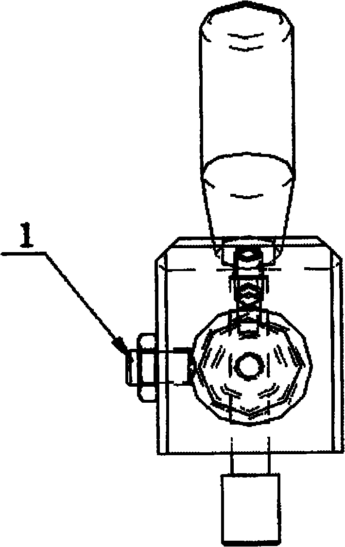
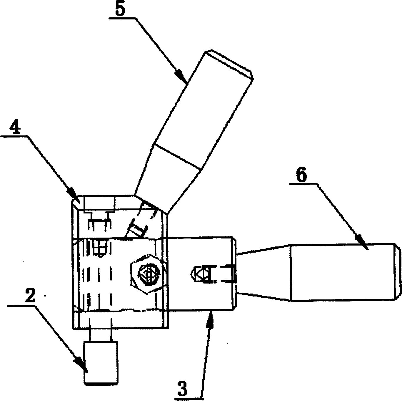
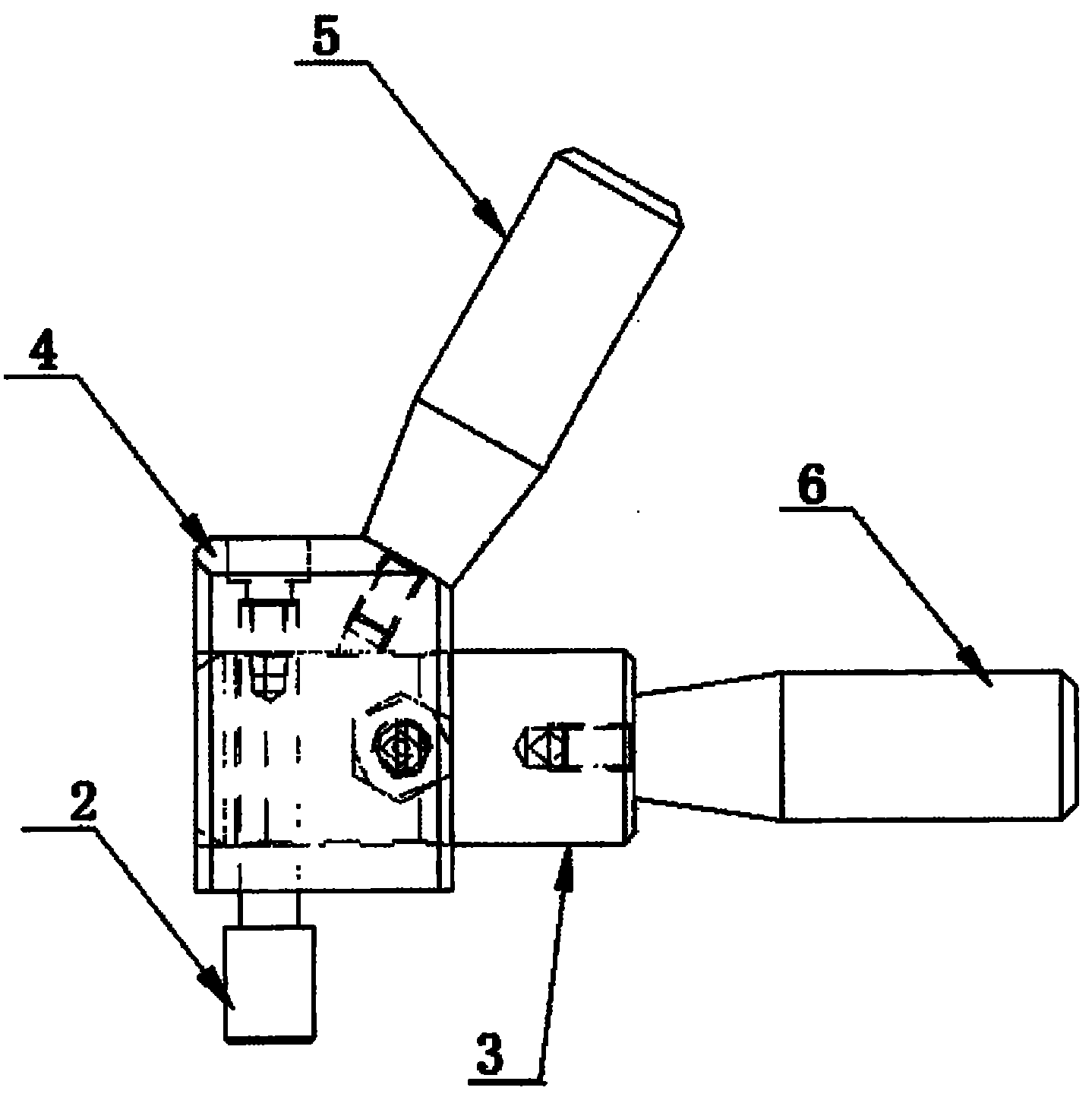
[0011] Please also refer to figure 1 and figure 2 , a workpiece positioning fixture according to an embodiment of the present invention is used for fast positioning of square workpieces with holes, and includes a steel ball self-locking screw 1, a fixture positioning pin 2, a product positioning pin 3, and a positioning block 4 , a first handle 5 and a second handle 6.

[0012] In this embodiment, the positioning block 4 is driven to move by turning the first handle 5 for positioning, and when the fixe...


PUM


Abstract

The invention relates to a workpiece positioning clamp used for quickly positioning a square workpiece with a hole. The clamp comprises a steel ball self-locking bolt, a clamp positioning pin, a product positioning pin, a positioning block, a first handle and a second handle. The workpiece positioning clamp has the advantages of simple structure and quick positioning.

Description

【Technical field】 [0001] The invention relates to a workpiece positioning fixture, in particular to a workpiece positioning fixture for fast positioning of a square workpiece with holes. 【Background technique】 [0002] In the production process, many processes are involved. In the process of continuous improvement of quality requirements and efficiency requirements, fixtures play an important role in it. However, in the prior art, the fixture for positioning the workpiece is complex in design and relatively slow in operation. To a certain extent, man-hours are wasted and costs are increased. [0003] Therefore, designing a clamp that can overcome the above-mentioned defects has become a technical problem to be solved urgently in this technical field. 【Content of invention】 [0004] In order to solve the above-mentioned shortcomings of the prior art, the object of the present invention is to provide a clamp. [0005] In order to achieve the above object, the technical s...

Claims


Application Information

Patent Timeline
IPC IPC(8): B25B11/00
Inventor 毛吉亮
Owner SUZHOU NEW DISTRICT KEXING WILL ELECTRONICS
Learn More