Double station turning device for machine special for circumferential welding of automobile transmission shaft
A turning device and transmission shaft technology, applied in auxiliary devices, manufacturing tools, welding equipment, etc., can solve the problems of low production efficiency and inability to meet the requirements of large-scale production of transmission shafts, and achieve the goal of speeding up the processing cycle and improving production efficiency Effect
- Summary
- Abstract
- Description
- Claims
- Application Information
AI Technical Summary
Problems solved by technology
Method used
Image
Examples
Embodiment 1
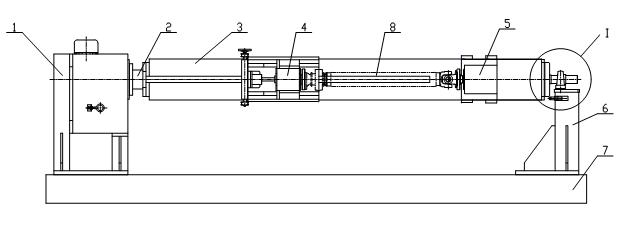
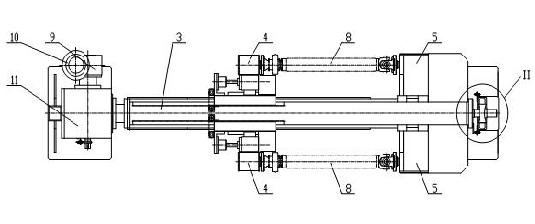
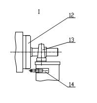
[0031] see figure 1 , figure 2 , image 3 with Figure 4 , the dual-station turning device of the automobile drive shaft ring welding machine includes a mounting base plate (7), which is characterized in that a dividing head bracket (1) is installed on the left side of the mounting base plate (7), and a bearing bracket (6) is installed on the right side. , a cam indexing box (11) is installed on the indexing head bracket (1), the input shaft of the cam indexing box (11) is connected to a motor (9) through a worm gear reducer (10), and the cam indexing A connecting flange (2) is installed on the output shaft of the degree box (11); a bearing with seat (13) is installed on the bearing bracket (6), and the bearing with seat (13) supports a flange shaft (12 ); install an overturning beam assembly (3) between the connecting flange (2) and the flange shaft (12); there are two head frame assemblies (4) that can be slidably displaced and symmetrically installed on the overturning ...
Embodiment 2
[0033] This embodiment is basically the same as Embodiment 1, and the special features are as follows: see Figure 5~9, the structure of the flip beam assembly (3) is: a square tube (3-1) has square holes or round holes on the upper and lower sides, and a mounting plate (3-2) is welded on the front and rear sides; The side plate (3-3) and a right side plate (3-4) are respectively welded to the left and right ends of the square tube (3-1); each of the two mounting plates (3-2) has a long A keyway, one guide key (3-5) is installed in each of the two long keyways, and the two head frame components (4) can be slidably displaced and symmetrically installed on two mounting plates (3-5) through the two guide keys (3-5) -2) on; four racks (3-6) are fixedly mounted on the four corners of the square tube (3-1). see Figure 10 with Figure 11 , the structure of the head frame assembly (4) is: a head frame bottom plate (4-1) is fixedly connected with two clip bars (4-19) to form a C-sh...
Embodiment 3
[0035] see figure 1 , a double-station overturning device for a transmission shaft girth welding machine, including a motor (9), a worm gear reducer (10), a cam indexing box (11), an indexing head bracket (1), a connecting Flange (2), a flip beam assembly (3), two headstock assemblies (4), two tailstock assemblies (5), a flange shaft (12), a seated bearing (13), a bearing bracket (6), two travel switches (14), two overturning in-position detection sensors (15), two sensor mounts (16), a sending board (17) and a mounting base (7). The dividing head bracket (1) and the bearing bracket (6) are installed on the installation base (7); the cam indexing box (11) is fixedly installed on the dividing head bracket (1), and the motor (9) passes through The worm gear reducer (10) is installed on the input shaft of the cam indexing box (11); the left side of the flip beam assembly (3) is installed on the cam indexing box (11) through the connecting flange (2) On the output shaft of the f...
PUM
 Abstract
Description
Claims
Application Information
 - R&D
- Intellectual Property
- Life Sciences
- Materials
- Tech Scout
- Unparalleled Data Quality
- Higher Quality Content
- 60% Fewer Hallucinations
Browse by: Latest US Patents, China's latest patents, Technical Efficacy Thesaurus, Application Domain, Technology Topic, Popular Technical Reports.
© 2025 PatSnap. All rights reserved.Legal|Privacy policy|Modern Slavery Act Transparency Statement|Sitemap|About US| Contact US: help@patsnap.com


