Multipoint temperature measuring device for thermoelectric refrigerating assembly

A technology of thermoelectric refrigeration and multi-point temperature, which is applied in the direction of measuring devices, electric devices, and thermometers using electric/magnetic elements that are directly sensitive to heat. Solder joints, weak galvanic couples, etc., to save manpower, facilitate heat collection, and improve accuracy

Inactive Publication Date: 2011-06-01
CHINA ELECTRONIC TECH GRP CORP NO 18 RES INST
View PDF0 Cites 3 Cited by
  • Summary
  • Abstract
  • Description
  • Claims
  • Application Information

AI Technical Summary

Problems solved by technology

At present, under the premise that the temperature of the hot surface of the cooling component is constant, the method of testing the temperature of the center and four corners of the cold surface of the thermoelectric cooling component is to use a thermometer to test different points separately. Because it is impossible to test all points at the same time, it cannot be accurately screened. Galvanic couples with weak solder joints may not be removed in time, resulting in irreparable losses due to failure of thermoelectric cooling components

Method used


Image

  • Multipoint temperature measuring device for thermoelectric refrigerating assembly
  • Multipoint temperature measuring device for thermoelectric refrigerating assembly
  • Multipoint temperature measuring device for thermoelectric refrigerating assembly

Examples


Embodiment Construction

[0020] The present invention will be further described in detail below in conjunction with the accompanying drawings and through specific embodiments. The following embodiments are only descriptive, not restrictive, and cannot limit the protection scope of the present invention.

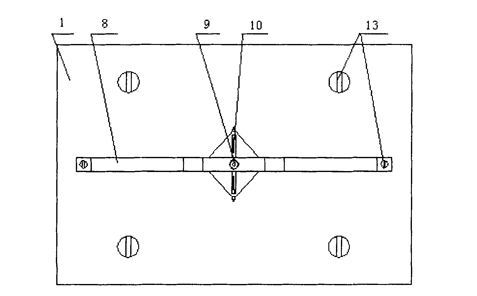
[0021] The multi-point temperature test device for thermoelectric refrigeration components is innovative in that it includes a housing 1, a positioning plate 2 fixed on the housing by fastening bolts 13, a boss-shaped temperature control platform 6 and a bracket 8, the positioning board and the convex There is a water jacket 3 and a temperature control refrigeration assembly 5 between the temperature control platforms from bottom to top; the top of the water jacket is close to the hot surface of the temperature control refrigeration assembly, and the cold surface of the temperature control refrigeration assembly is close to the temperature control platform. Below; there is a threaded support 9 on the ...


PUM


Abstract

The present invention relates to a multipoint temperature measuring device for a thermoelectric refrigerating assembly, comprising an outer shell, a locating plate, a boss-shaped temperature controlling platform and a support, wherein the locating plate, the boss-shaped temperature controlling platform and the support are fastened to the outer shell with fastening bolts respectively; a water jacket and a temperature controlling refrigerating assembly are arranged between the locating plate and the boss-shaped temperature controlling platform from bottom to top. The upper face of the water jacket clings to the hot face of the temperature controlling refrigerating assembly, and the cold face of the temperature controlling refrigerating assembly clings to the lower face of the temperature controlling platform. On the support is a pedestal moving up and down along a screw thread, the upper end of the pedestal is in the form of a screw and the lower end is a hollow body with screwed holes on the side surface, and a temperature measuring screw with a thermocouple in contact with the temperature controlling platform is positioned in the screw holes. Thermocouples in contact with the temperature controlling platform are arranged in the middle of the pedestal. By employing the temperature measuring screw and the pedestal moving along the thread up and down on the support, and the temperature measuring screw moving horizontally along the thread on the pedestal, simultaneous multipoint temperature measurements are realized and the galvanic couples with infirm welding spots are accurately identified and picked out, thus the irretrievable loss caused by the dysfunction of the thermoelectric refrigerating assembly because of the infirm welding spots of the galvanic couple can be effectively prevented.

Description

technical field [0001] The invention belongs to the technical field of a thermoelectric cooling component testing device, and in particular relates to a multi-point temperature testing device for a thermoelectric cooling component. Background technique [0002] The thermoelectric refrigeration component is a heat pump that uses the Seebeck effect. It is composed of a number of thermoelectric couples connected in series and thermally connected in parallel. It can be used for both cooling and heating. It is widely used in high-tech fields such as aviation and aerospace because of its advantages such as long life, no noise during operation, and precise temperature control when adjusting voltage or current. Under normal circumstances, under the premise that the temperature of the hot surface of the cooling component is constant, the temperature of the center of the cold surface of the cooling component and the four corners are the same. When the solder joints with galvanic coup...

Claims


Application Information

Patent Timeline
Patent Type & Authority Applications(China)
IPC IPC(8): G01K7/02G01K1/14
Inventor 安晓雨
Owner CHINA ELECTRONIC TECH GRP CORP NO 18 RES INST
Why Eureka
Try Eureka