
Vane pump

A vane pump and vane technology, used in pumps, pump components, rotary piston pumps, etc., can solve the problems of increased cost, difficult vanes to quickly extend, and need to be replaced, and achieve low manufacturing costs, superior performance, and reliable performance. Effect

Active Publication Date: 2011-05-25
BOSCH AUTOMOTIVE DIESEL SYST
View PDF0 Cites 12 Cited by
  • Summary
  • Abstract
  • Description
  • Claims
  • Application Information

AI Technical Summary

Problems solved by technology

However, in the case of using spring force, not only the structure of the pump is complicated, but also the spring is easy to wear and needs to be replaced, thus increasing the manufacturing and maintenance costs of the pump
In the case of using centrifugal force, since the size of the centrifugal force depends on the rotating speed of the rotor, it is difficult to realize the rapid extension of the blade when the pump is running at low speed
In the case of using high-pressure hydraulic pressure, it is necessary to supply high-pressure liquid to the inner end of the blade, which will also increase the cost of the pump, and it is difficult to efficiently realize the rapid extension of the blade

Method used


Image

  • Vane pump
  • Vane pump
  • Vane pump

Examples


Embodiment Construction

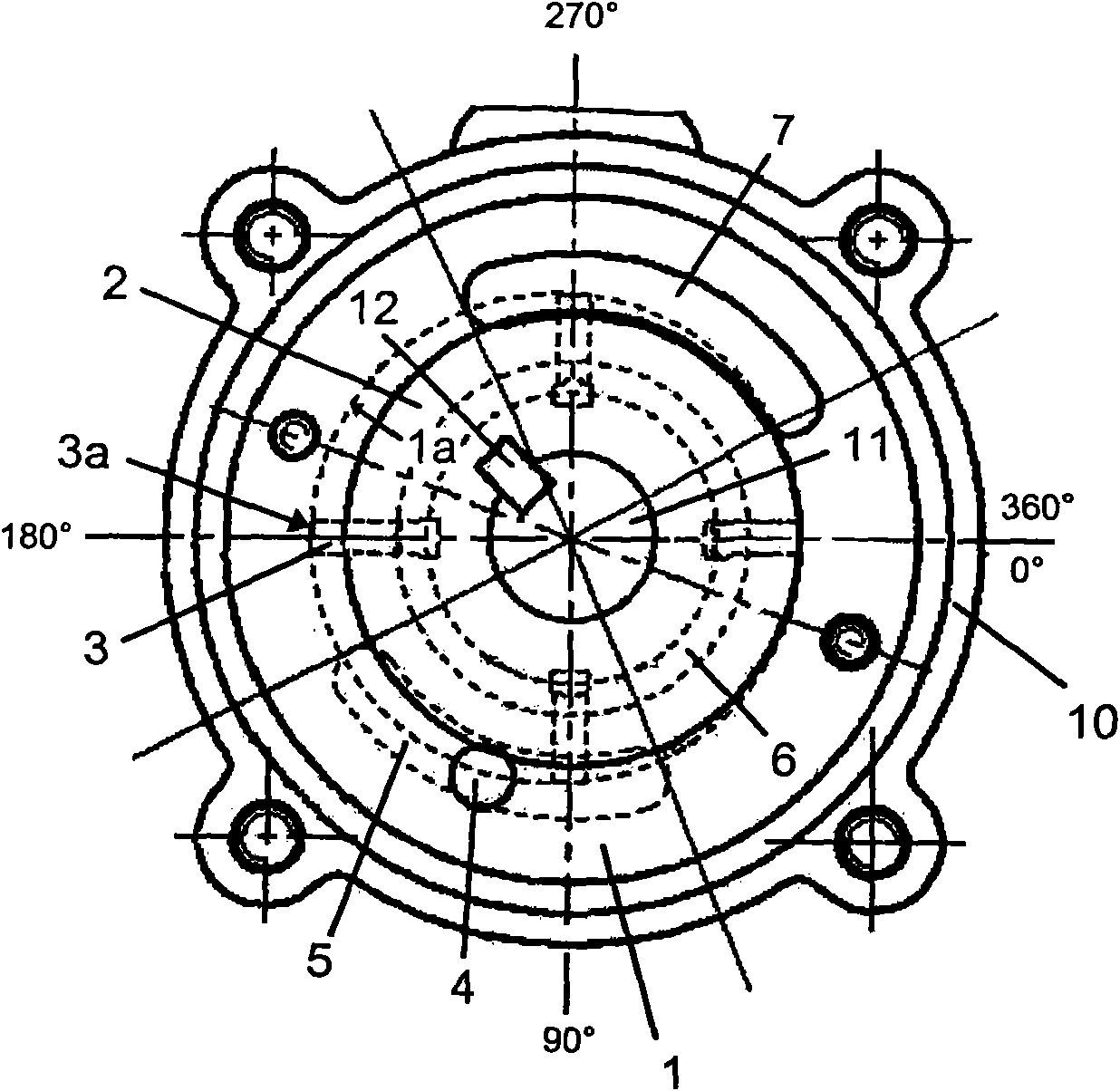
[0026] Preferred embodiments of the vane pump of the present invention are described below with reference to the accompanying drawings. In the example shown in the figure, the vane pump is a fuel pump used in an engine system to supply fuel. Obviously, the application of the present invention is not limited thereto.

[0027] like figure 1 As shown, a vane pump according to the invention comprises a housing 10, a stator 1 fixed in the housing and a rotor 2 eccentrically accommodated in the stator. A plurality of vane slots are radially formed in the rotor 2, and the vanes 3 can reciprocally protrude and retract in the respective vane slots. An oil inlet 4 is formed in the stator 1, an oil inlet arc groove 5 communicated with the oil inlet 4, an oil discharge arc groove 7 set as a mirror image of the oil inlet arc groove 5, and an oil discharge arc groove 7 Connected oil outlet (not shown in the figure). The oil inlet arc groove 5 and the oil discharge arc groove 7 communica...


PUM


Abstract

The invention relates to a vane pump, which comprises a stator where an oil inlet arc-shaped groove and an oil discharge arc-shaped groove are formed, a rotor eccentrically accommodated in the stator, a plurality of vane grooves radially formed in the rotor and a plurality of vanes, wherein each vane is respectively suitable for stretching out and returning in corresponding vane groove in a reciprocated manner. A circular oil duct is formed in the rotor or in a side plate on one side of the rotor, communicated with the oil discharge arc-shaped groove on the one hand and with the rear end of each vane groove on the other hand for applying oil discharge side pressure on the inner end surface of the vane so that the differential pressure between the inner and the outer end surfaces of the vane is generated when the pump is started at a low speed. The upstream end of the oil inlet arc-shaped groove is arranged in a position of zero clearance rotating along with the rotary direction for 90 degrees plus a lag angle of relative to a zero degree position. The invention has the advantages of excellent vane pump performance, simple structure, low manufacturing cost and reliable performance.

Description

technical field [0001] The present invention relates to a vane pump having improved vane extension capability at low rotational speeds. Background technique [0002] Vane pumps are widely used in various equipment to provide hydraulic fluid, such as fuel oil, at a certain pressure and flow rate required by the equipment. A conventional vane pump comprises a stator and a rotor accommodated eccentrically in the stator. A plurality of vane slots are radially formed in the rotor, and the vanes can reciprocally protrude and retract in the respective vane slots. As the rotor is driven to rotate, the outer end of each vane is in sliding contact with the inner peripheral surface of the stator. In this way, each working chamber enclosed by the inner peripheral surface of the stator, the outer peripheral surface of the rotor and the blades undergoes a volume change, and the fuel sucked into the stator from the inlet is pressurized by the blades protruding from the outer peripheral s...

Claims


Application Information

Patent Timeline
Patent Type & Authority Applications(China)
IPC IPC(8): F04C2/344F04C15/00
CPCF04C2/3442F04C2210/1044F01C21/0863
Inventor 沈志彬
Owner BOSCH AUTOMOTIVE DIESEL SYST
Learn More