Accelerator control device of micro-cultivator

A technology of throttle control and micro-tiller, which is applied in the field of micro-tiller, can solve the problems of poor positioning of the adjustment handle, poor controllability of the micro-tiller, and lack of better limit, so as to achieve simple connection and Reliable, simple and novel structure, low manufacturing cost

Inactive Publication Date: 2012-11-07
周树明 +1
View PDF0 Cites 0 Cited by
  • Summary
  • Abstract
  • Description
  • Claims
  • Application Information

AI Technical Summary

Problems solved by technology

At present, most micro tillage machines realize walking and parking by installing a throttle control device on the micro tiller. This kind of throttle control device mainly includes a mounting seat, a positioning plate is arranged on the mounting seat, and a limit position is set above the positioning plate. The mounting seat, the positioning plate and the limiting plate are fixed through the same adjusting bolt, and an adjusting handle is installed between the positioning plate and the limiting plate, and the adjusting handle is covered on the adjusting bolt, and the The adjusting handle can be rotated around the adjusting bolt, and the adjusting handle is provided with a throttle cable, and the acceleration, idling and parking of the tiller can be realized by toggling the adjusting handle, but the adjusting handle is not well developed in this structure. When the micro-tiller is controlled by other control mechanisms of the micro-tiller such as the parking handle to achieve idle speed and other states, because the adjustment handle has not been well limited, it will directly jump to the parking state, thus making the micro-tiller The machine stops, so the micro tillage machine has the disadvantages of poor controllability and so on.

Method used


Image

  • Accelerator control device of micro-cultivator
  • Accelerator control device of micro-cultivator
  • Accelerator control device of micro-cultivator

Examples


Embodiment Construction

[0012] Below in conjunction with accompanying drawing and embodiment the present invention will be further described:

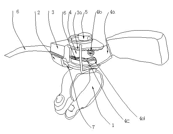
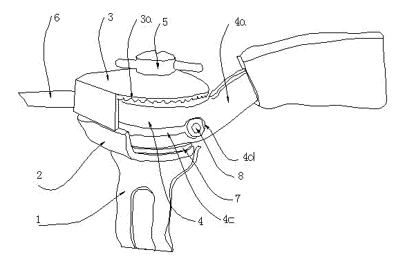
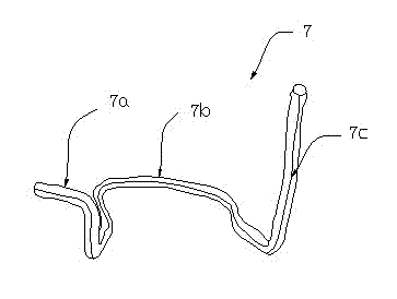
[0013] Such as Figure 1 ~ Figure 3 A throttle control device for a tiller shown includes a mounting base 1, a positioning plate 2 is arranged on the mounting base 1, a limiting plate 3 is provided above the positioning plate 2, and the mounting base 1, positioning plate 2 and The limiting plate 3 is fixed through the same adjusting bolt 5, and an adjusting handle 4 is installed between the positioning plate 2 and the limiting plate 3. The adjusting handle 4 is covered on the adjusting bolt 5, and the adjusting handle 4 can rotate around the adjusting bolt 5, and the adjusting handle 4 is provided with an accelerator cable 6, that is, a circumferential groove 4c is opened in the circumferential direction of the adjusting handle 4, and a cable hole 4d is opened on the handle 4a , one part of the accelerator cable 6 protrudes from the limit plate 3, and the ot...


PUM


Abstract

The invention discloses an accelerator control device of a micro-cultivator. A mounting base, a locating plate and a spacing plate successively arranged from bottom to top are penetrated and fixed by the same adjusting bolt; an adjusting handle is installed between the locating plate and the spacing plate and covers on the adjusting bolt; the adjusting handle is provided with an accelerator stay wire; a spacing snap ring is arranged between the mounting base and the locating plate and is integrally composed of a left clamping part, a middle fixing part and a right spacing part, wherein the middle fixing part is fixed between the mounting base and the locating plate; the left clamping part is clamped on the locating plate; the right spacing part is positioned on one side of the handle partof the adjusting handle; and the left clamping part and the right spacing part are positioned on the same side of the handle part. The accelerator control device can better realize that the micro-cultivator can be reliably accelerated, idled and stopped, thus improving the maneuverability of the micro-cultivator. The accelerator control device has the characteristics of good safety performance, low manufacture cost and the like, and is simple and convenient in operation.

Description

technical field [0001] The invention relates to a tiller, in particular to a throttle control device for the tiller. Background technique [0002] In rural China, micro tillage machines are used more and more widely, and they play an increasingly important role in plowing, plowing, and cultivation. However, during the use of the tiller, many accidents have occurred, such as overturning when encountering obstacles, unskilled operators, operator tripping or other unexpected situations, so it is urgent to improve the controllability of the tiller . At present, most micro tillage machines realize walking and parking by installing a throttle control device on the micro tiller. This kind of throttle control device mainly includes a mounting seat, a positioning plate is arranged on the mounting seat, and a limit position is set above the positioning plate. The mounting seat, the positioning plate and the limiting plate are fixed through the same adjusting bolt, and an adjusting h...

Claims


Application Information

Patent Timeline
Patent Type & Authority Patents(China)
IPC IPC(8): F02D33/00F02D29/00
Inventor 周树明张坤
Owner 周树明
Why Eureka
Try Eureka