
Transport device for conveying printed products

一种传输机构、印刷品的技术,应用在输送机、运输和包装、物件供给等方向,达到安装简单的效果

Inactive Publication Date: 2011-05-18
MULLER MARTINI HLDG
View PDF14 Cites 3 Cited by
  • Summary
  • Abstract
  • Description
  • Claims
  • Application Information

AI Technical Summary

Problems solved by technology

In addition, the technical problem to be solved by the present invention is to decisively prolong the service life of a conveyor chain composed of several chain links and to minimize the noise during its operation

Method used


Image

  • Transport device for conveying printed products
  • Transport device for conveying printed products
  • Transport device for conveying printed products

Examples


Embodiment Construction

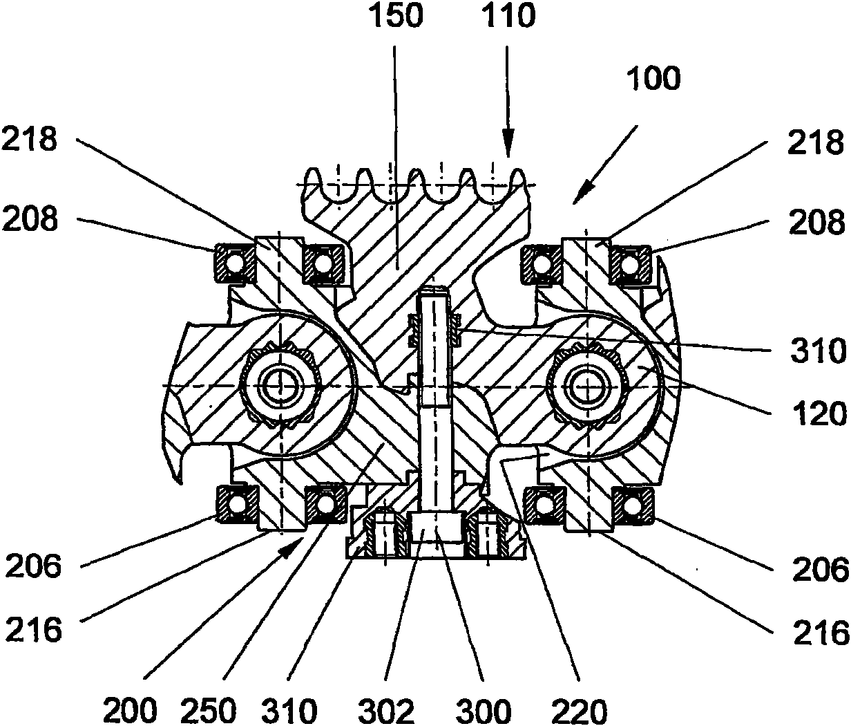
[0041] The conveyor chain shown in the drawing comprises a functional part in the form of a first chain link 100 and a second chain link 200 . Each first link 100 has a comb-shaped coupling zone 110 for coupling the conveyor chain to the drive chain 530 (see Figure 11 )superior. Each second chain link 200 has a total of four guide rollers 202, 204, 206, 208, wherein the guide rollers 206 and 208 are mounted rotatably about a first common roller axis and the guide rollers 202, 204 are rotatably arranged about a second common roller axis. The shaft is rotationally positioned. The first and second rollers extend perpendicular to each other and are arranged in one plane. Each first chain link 100 is arranged between two second chain links 200 . In this case, each first chain link 100 is rigidly connected on the one hand to a second chain link 200 to form a functional device and on the other hand is connected to another second chain link 200 to form a joint arrangement.

[004...


PUM


Abstract

The invention relates to a transport device for conveying printed products, wherein the transport device essentially consists of a conveying chain configured for a predetermined section. The conveying chain is essentially composed of a number of functional units which are coupled to each other. The conveying chain itself consists of at least two functional units which are arranged essentially sequential along the conveying section and form a rigid and / or an articulated connection. The functional unit is composed of a first chain link (100) and a second chain link (200), which are operatively connected to each other and differing in respective functions. In order to form the conveying chain, the functional units are configured congruent or quasi-congruent or the like in the sequence, or the functional units are configured different with respect to functionality. The functional units are provided with means or connecting elements for creating a detachable connection, or a conditionally detachable connection due to traction, and / or a non-detachable connection.

Description

technical field [0001] The invention relates to a conveying mechanism for conveying printed matter, wherein the conveying mechanism essentially comprises a conveying chain designed for a predetermined route section, said conveying chain essentially comprising a plurality of functional units which can be coupled to one another. Background technique [0002] Conveyor chains of this type are used to transport printed products between individual processing stations such as insertion machines, addressing devices, gluing equipment, etc. In this case, the printed product is usually held by grippers attached to the chain links and possibly released from the grippers in a processing station. To ensure continuous operation, the chain links of the conveyor chain can usually be driven in a continuous cycle along the conveying path. The conveyor chain is guided along the conveyor path with suitable guides or guide rails, which can also define the curve of the conveyor path. In order to...

Claims


Application Information

Patent Timeline
Patent Type & Authority Applications(China)
IPC IPC(8): B65G17/38
CPCB65H2403/30B65H2404/33B65G23/16B65H5/085B65H2404/31
Inventor J-C·奥普利格M·兰多尔特T·克鲁泽
Owner MULLER MARTINI HLDG
Learn More