
Method and device for conveying compressed gas

A gas and compression stage technology, which is used in the field of conveying compressed gas and devices, and can solve problems such as unused

Active Publication Date: 2013-09-11
LEOBERSDORFER MASCHFAB GMBH & CO
View PDF2 Cites 0 Cited by
  • Summary
  • Abstract
  • Description
  • Claims
  • Application Information

AI Technical Summary

Problems solved by technology

The disadvantage here is, in particular, that the energy used for compressing the air is discharged unused into the surroundings after the leak test has been completed

Method used


Image

  • Method and device for conveying compressed gas
  • Method and device for conveying compressed gas
  • Method and device for conveying compressed gas

Examples


Embodiment Construction

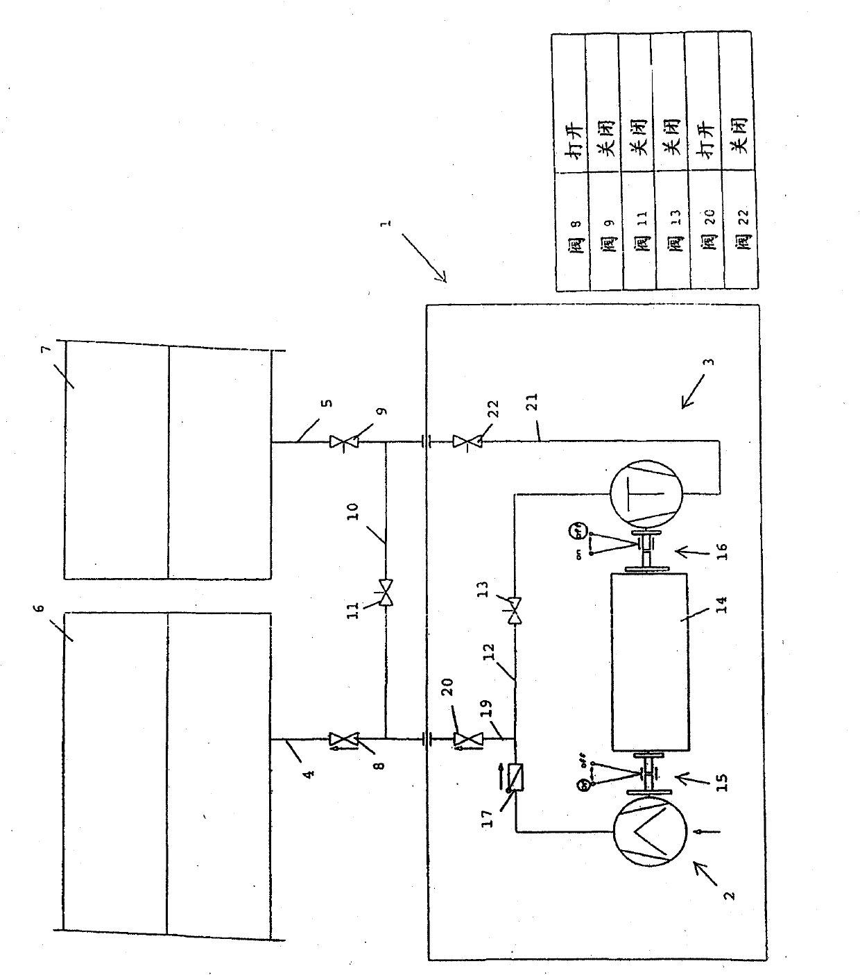
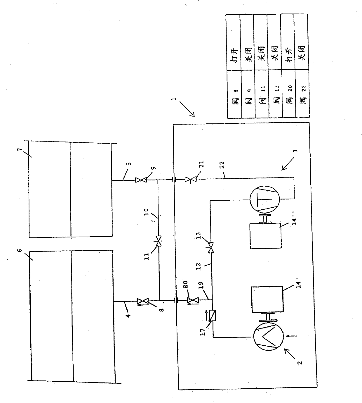
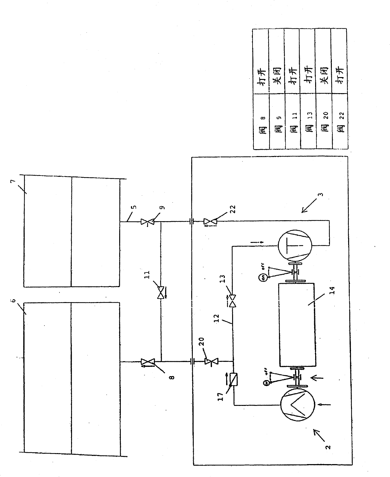
[0028] figure 1 and Figure 1a A compressor 1 with a low-pressure stage 2 and a high-pressure stage 3 is shown in . The compressor 1 is connected via a first gas supply line 4 to a first line section 6 and via a second gas supply line 5 to a second line section 7 . A shut-off valve 8 or 9 is provided in each gas delivery line 4 , 5 so that the intake and exhaust flow through the two gas delivery lines 4 , 5 can be selectively controlled. The two gas supply lines 4 , 5 are connected to one another via a bypass line 10 , which also has a shut-off valve, ie, a bypass valve 11 .

[0029] The two compression stages, ie the low-pressure compression stage 2 and the high-pressure compression stage 3 , are connected to each other via a compression line 12 , in which a shut-off valve, ie, a compression valve 13 , is likewise provided. In the illustrated embodiment, a screw compressor 2 is provided as the low-pressure compression stage 2 and a reciprocating piston compressor is provid...


PUM


Abstract

The invention relates to a method and device for conveying compressed gas into at least two mutually separate pipeline sections (6, 7), wherein gas is compressed and conveyed into a first pipeline section (6), a connection is subsequently produced between the two pipeline sections (6, 7) such that the compressed gas flows from the first pipeline section (6), on account of the excess pressure, into a second pipeline section (7), and gas from the first pipeline section (6) is subsequently compressed and conveyed into the second pipeline section (7).

Description

technical field [0001] The invention relates to a method for conveying compressed gas into at least two mutually separated pipeline sections and a device for conveying compressed gas into at least two mutually separated pipeline sections, said device having at least A compressor, each of which is connected to the pipeline section via a gas delivery pipeline, wherein each of the two gas delivery pipelines has a valve. Background technique [0002] In order to check the tightness of pipelines, especially pipelines, the individual sections are subjected to a pressure test / pressurization test (Abdrücken), i.e. the pipeline section is filled with compressed gas and after a defined period of time it is determined whether the pressure is maintained or A pressure loss occurs. [0003] To this end, conventional gases, in particular air, have hitherto been introduced into a first line section in which a tightness test is carried out, and then the gas, which is usually compressed in t...

Claims


Application Information

Patent Timeline
Patent Type & Authority Patents(China)
IPC IPC(8): F04B23/04F04B23/10F04B25/00F04B41/06F04B51/00
CPCF04B41/06F04B51/00F04B23/04F04B25/00F04B23/10F04B49/007
Inventor E·胡塔T·霍因梅塞
Owner LEOBERSDORFER MASCHFAB GMBH & CO
Learn More