
Family of cutting inserts, milling cutting tool, and cutting insert

一种切削刀片、铣削刀具的技术,应用在铣削切削刀片、铣刀、成型刀等方向,能够解决径向切削力震颤等问题

Active Publication Date: 2011-05-04
SECO TOOLS AB
View PDF1 Cites 3 Cited by
  • Summary
  • Abstract
  • Description
  • Claims
  • Application Information

AI Technical Summary

Problems solved by technology

This approach tends to generate high radial cutting forces which are acceptable when the tool overhang is small, but which can produce chattering effects when the overall length of the tool is large

Method used


Image

  • Family of cutting inserts, milling cutting tool, and cutting insert
  • Family of cutting inserts, milling cutting tool, and cutting insert
  • Family of cutting inserts, milling cutting tool, and cutting insert

Examples


Embodiment Construction

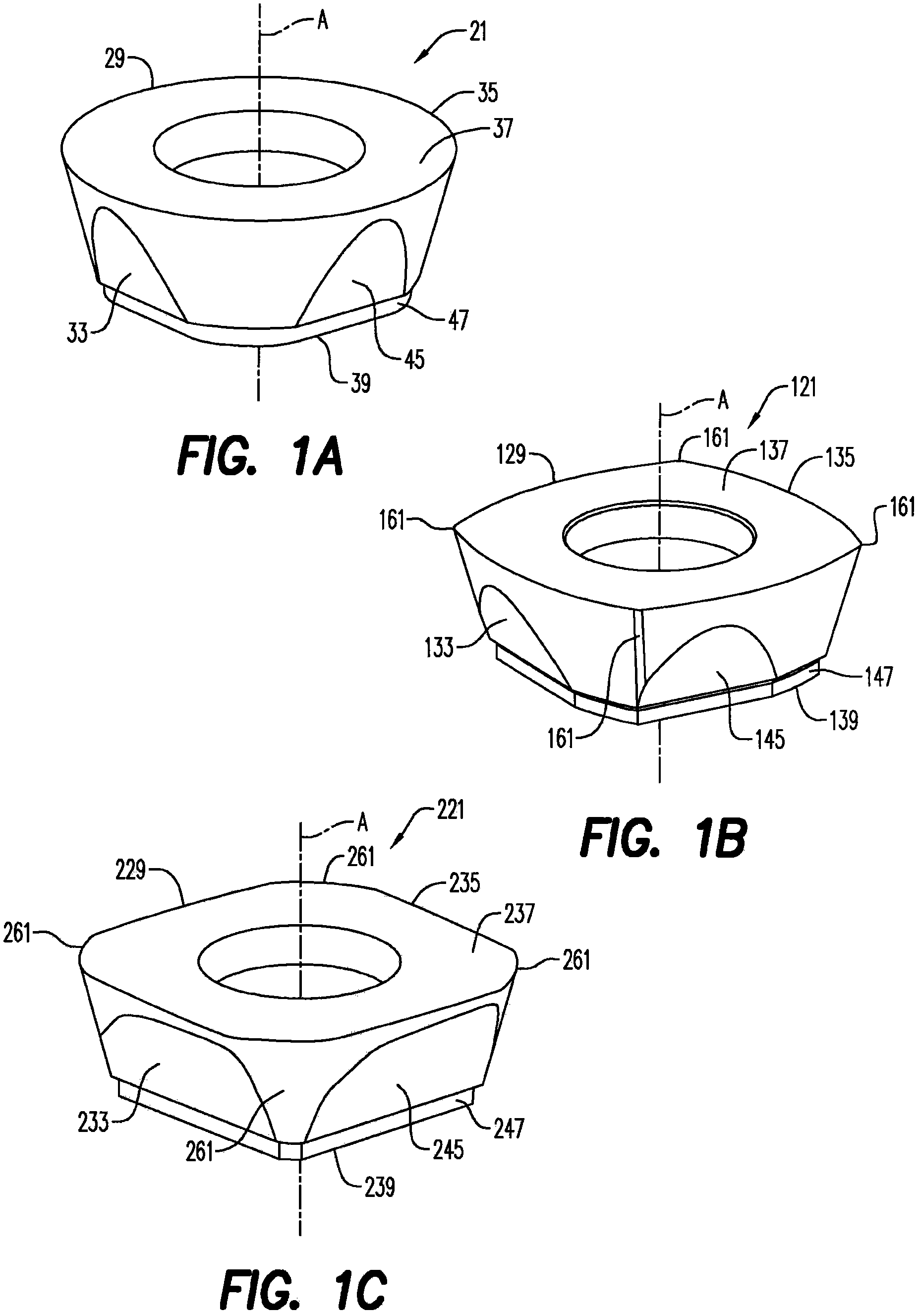
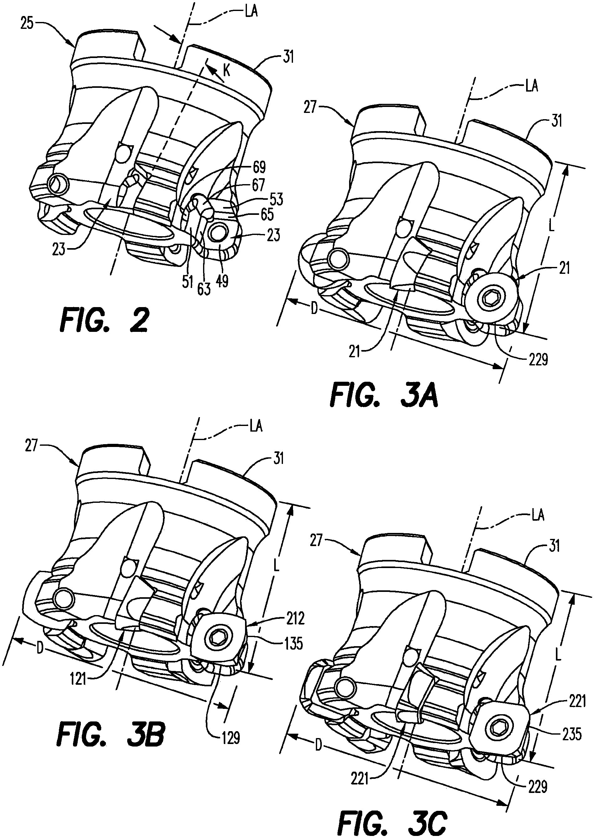
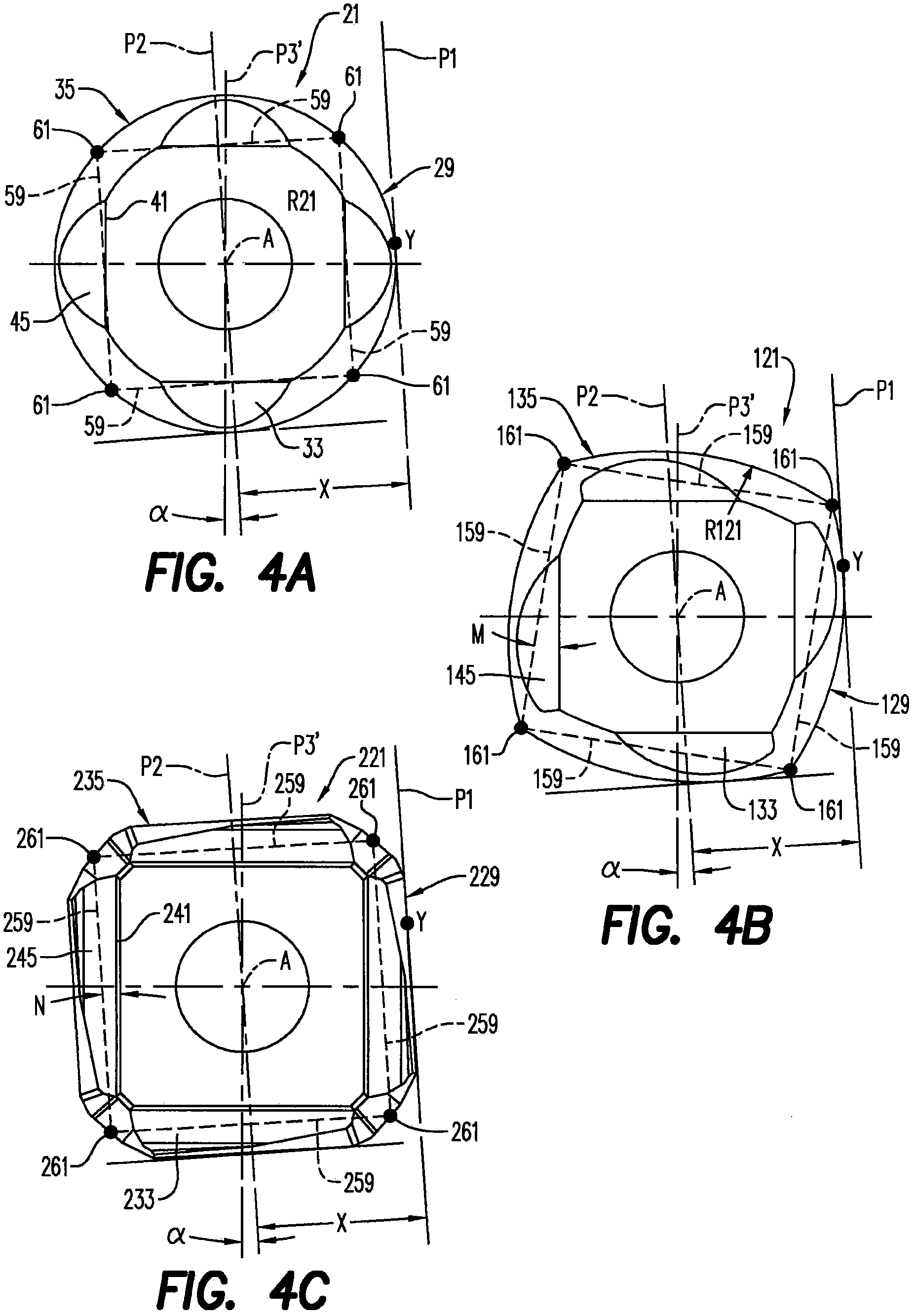
[0021] The different inserts 21, 121, 221 of the cutting insert set are shown in Figures 1A-1C. Each blade 21 , 121 , 221 has a different geometry, for example, but not necessarily, a cutting edge that is differently shaped when viewed in top view. For purposes of illustration, blade 21 has a circular shape when viewed in plan view; The diameter of the circle and the corners between the cutting edges are rounded; the blade 221 has a generally quadrilateral (with four sides) shape when viewed in plan view, the radius of the cutting edge is larger than the diameter of the circle defined in the blade , and have multiple (three) chamfers between the cutting edges. Differences in geometry may involve other features of the insert, either as an alternative or in addition to the cutting edge, such as the presence or absence of chip breakers, flat or curved wiper surfaces, etc.

[0022] Each of the plurality of different inserts 21, 121, 221 is configured to be adapted to be mounted ...


PUM


Abstract

A family of cutting inserts includes a plurality of different inserts, each having a different geometry. Each insert of the plurality of different inserts is adapted to be mounted in a common insert-receiving pocket on a toolholder of a milling cutting tool so that an outer diameter generated by the milling cutting tool is the same, regardless which insert of the plurality of inserts is mounted in the pocket.

Description

technical field [0001] The present invention relates generally to cutting inserts and in particular to cutting insert sets usable in the same tool holder. Background technique [0002] In milling operations, the use of round shaped inserts can provide a depth of cut equal to half the insert diameter, or create a radiused arc at the bottom of the workpiece. The lead angle of milling tools with round inserts depends on the depth of cut. The greater the depth of cut, the greater the chamfer. To achieve maximum material removal rates with round inserts, the traditional approach is to use large depths of machining and avoid reaching high feeds per tooth. This approach tends to generate high radial cutting forces, which are acceptable when the tool overhang is small, but which produce chattering effects when the overall length of the tool is large. [0003] For high-feed inserts, eg with four cutting edges, the maximum depth of cut is reduced due to the shape of the insert, and...

Claims


Application Information

Patent Timeline
Patent Type & Authority Applications(China)
IPC IPC(8): B23C5/02B23B51/00
CPCB23C5/202B23C2200/045B23C2200/125B23C2200/203B23C2210/168B23C5/06Y10T407/20Y10T407/23Y10T407/1924Y10T407/21B23C5/205B23C5/20
Inventor B·米舍莱B·里维埃C·朱布洛F·奥泽纳特
Owner SECO TOOLS AB
Learn More