Spring plate puncture forming device

A molding device and shrapnel technology, which is applied in the field of hardware molds, can solve the problems affecting the processing of shrapnel, and the shrapnel is easy to break holes, etc., and achieve the effects of convenient and accurate processing, good processing effect, and shortened processing time

Active Publication Date: 2011-04-27
KUNSHAN ESON PRECISION ENGINEERING CO LTD
View PDF6 Cites 2 Cited by
  • Summary
  • Abstract
  • Description
  • Claims
  • Application Information

AI Technical Summary

Problems solved by technology

[0004] In order to solve the problem in the prior art that the piercing position of the shrapnel is easy to break holes and affect the subsequent processing o...

Method used


Image

  • Spring plate puncture forming device
  • Spring plate puncture forming device
  • Spring plate puncture forming device

Examples


Embodiment Construction

[0019] The present invention will be further described below in conjunction with the accompanying drawings.

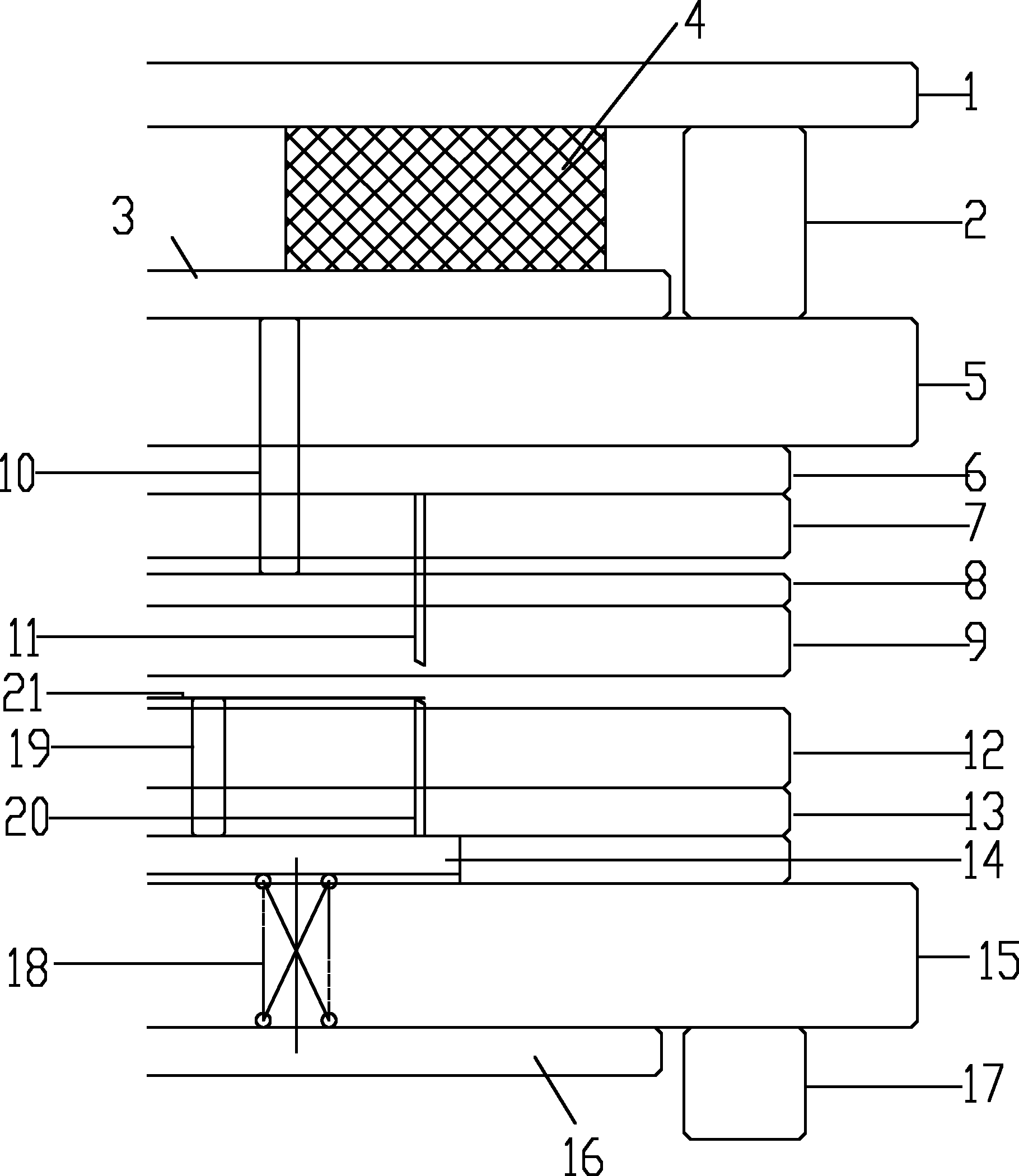
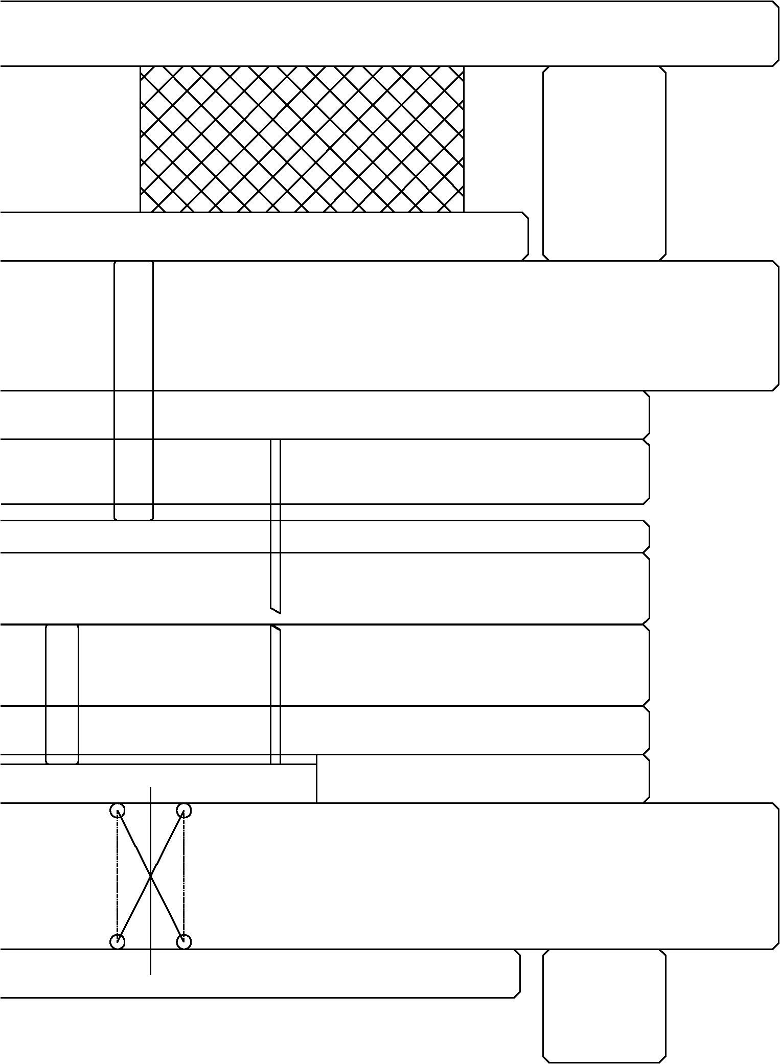
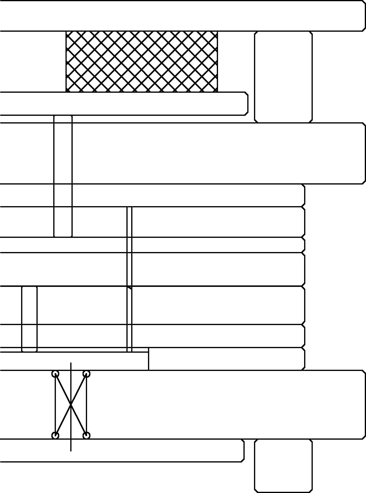
[0020] Such as figure 1 As shown, a shrapnel piercing forming device includes an upper supporting plate 1, an upper footing 2, an upper knockout plate 3, a rubber 4, an upper mold base 5, an upper backing plate 6, an upper splint 7, and an upper stop plate 8. Upper stripping plate 9, upper mold punching rod 10, piercing punch 11, lower template 12, lower backing plate 13, lower mold beating plate 14, lower mold base 15, lower knockout plate 16, lower pad 17, lower Die spring 18, lower mold beat bar 19, puncture interior and take off 20.

[0021] An upper foot 2 is fixedly arranged between the upper supporting plate 1 and the upper mold base 5 , and an upper backing plate 6 and an upper splint 7 are sequentially fixed on the bottom of the upper mold base 5 . Above the upper mold base 5, an upper knockout plate 3 is arranged next to the upper pad 2, and a unglue 4 is a...


PUM


Abstract

The invention discloses a spring plate puncture forming device which has the following beneficial effects: according to the sizes of the processed spring plates, the required number of springs are arranged below a lower die knock plate and the lower die knock plate is utilized to support puncture inner strippers. By means of the invention, the problem that when the spring plates are processed in the prior art, the puncture positions of the spring plates are liable to broken holes, thus affecting subsequence processing of the spring plates is solved. The spring plate puncture forming device issimple to operate, has high efficiency, can not cause broken holes, and utilizes the springs to ensure the plates to float up and down to replace ejector pins to strip materials.

Description

[0001] technical field [0002] The invention relates to a hardware mold, in particular to a piercing forming device for shrapnel. Background technique [0003] For the small and dense punctures in the NOKIA shrapnel, the existing puncture method is to use a thimble to puncture and remove the material. A spring is arranged under each punctured internal prolapse, and a thimble is arranged on the spring, and the thimble is used to remove the material. The support is pierced and dislodged. Because the punctures in the shrapnel are small and dense, during processing, two adjacent springs are too close together, which may easily cause puncture holes, affect the quality of the shrapnel being processed, and bring certain difficulties to subsequent processing and molding. trouble. Simultaneously, a spring and a thimble need to be arranged at the bottom of each punctured inner strip, and the parts are used more, and the cost is higher. In addition, the two adjacent springs are too...

Claims


Application Information

Patent Timeline
IPC IPC(8): B21D28/26
Inventor 黄崇信
Owner KUNSHAN ESON PRECISION ENGINEERING CO LTD
Why Eureka
Try Eureka