
Infinitely variable transmission device of a drive train of a vehicle

A technology of continuously variable speed and transmission equipment, which is applied to transmission devices, mechanical equipment, belts/chains/gears, etc., which can solve the problems of large structural expenses and high manufacturing costs, and achieve the effect of small structural space requirements

Inactive Publication Date: 2011-04-13
ZF FRIEDRICHSHAFEN AG
View PDF4 Cites 11 Cited by
  • Summary
  • Abstract
  • Description
  • Claims
  • Application Information

AI Technical Summary

Problems solved by technology

Furthermore, the effective connection between the sun gear of the planetary gear and the first shaft of the variator is realized by means of an undesirably long connecting shaft, which can only be realized by means of a bearing structure which is complex in construction and expensive to produce. used in the transmission

Method used


Image

  • Infinitely variable transmission device of a drive train of a vehicle
  • Infinitely variable transmission device of a drive train of a vehicle
  • Infinitely variable transmission device of a drive train of a vehicle

Examples


Embodiment Construction

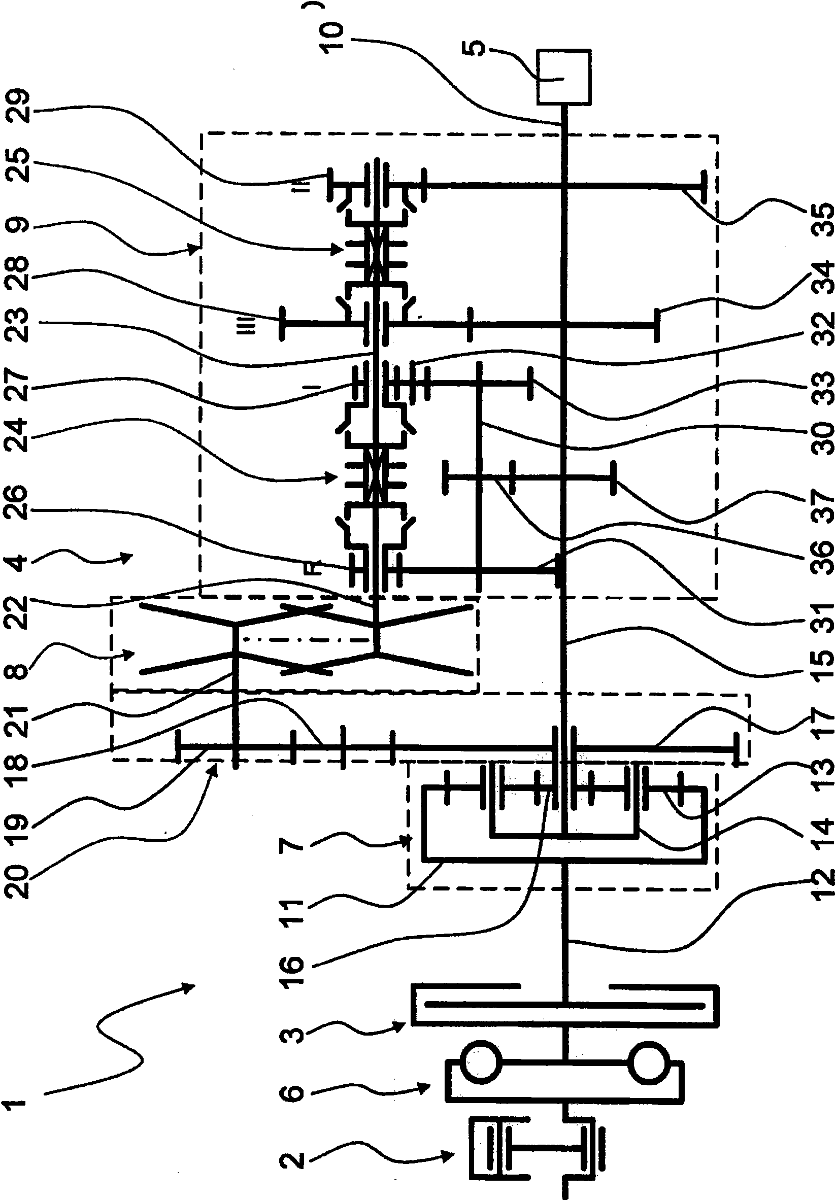
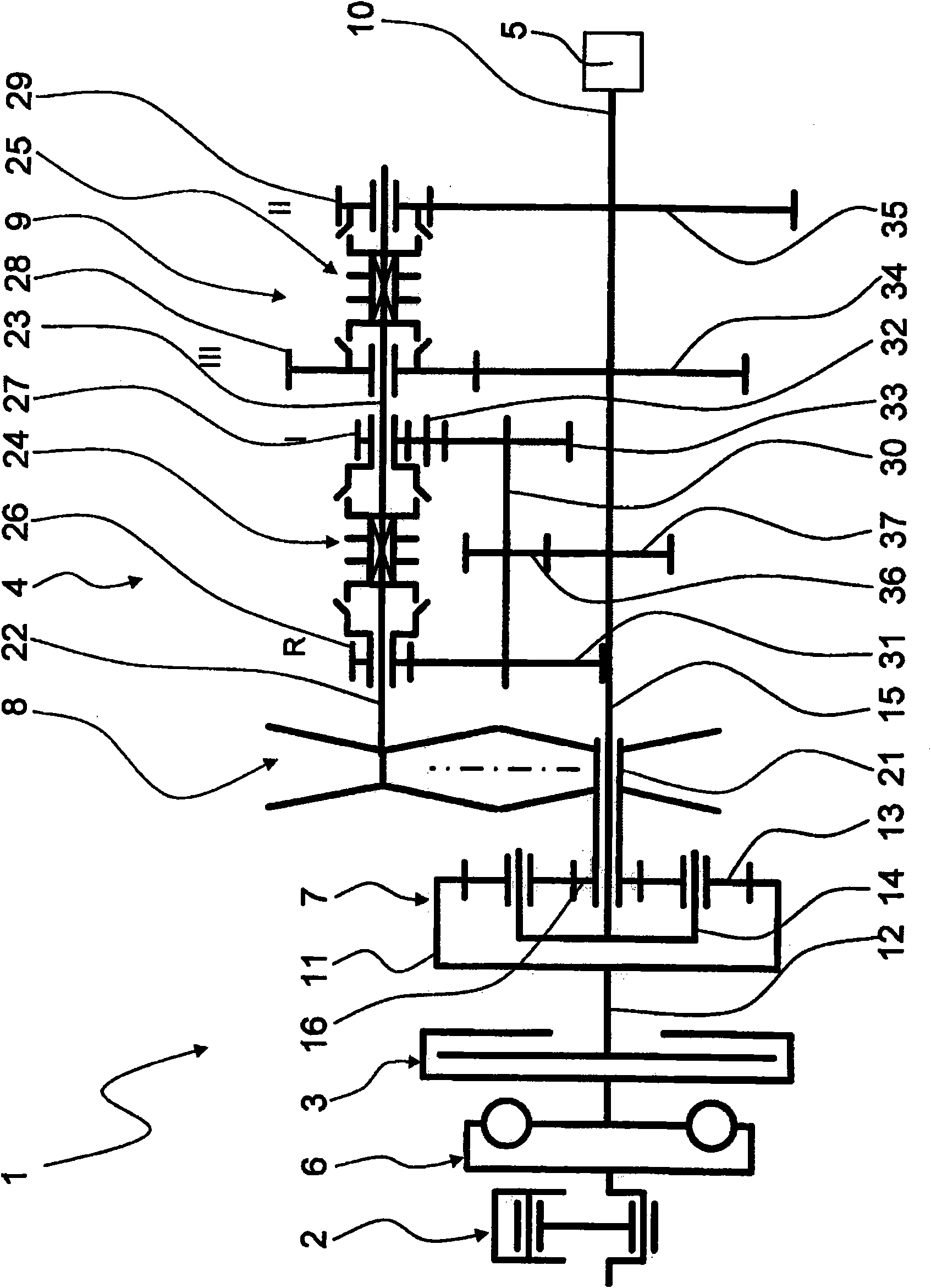
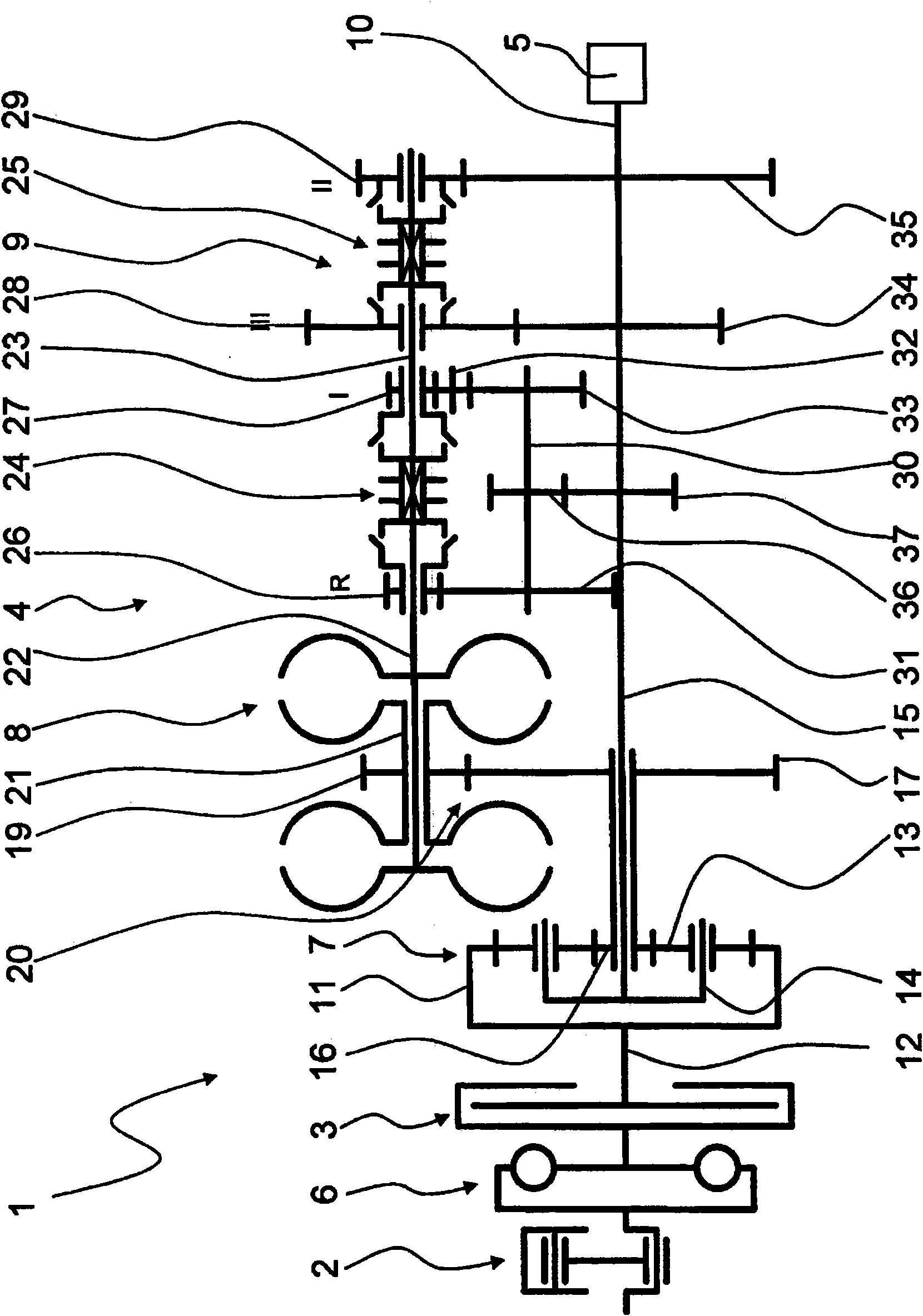
[0028] exist figure 1 1 shows in very schematic form a motor vehicle drive train 1 comprising an engine 2 , a starter 3 , a transmission 4 and an output shaft 5 . A so-called vibration damper 6 is arranged between the engine 2 and the starter 3 , here in the form of a friction clutch, by means of which vibration inhomogeneities of the engine 2 , here in the form of an internal combustion engine, can be damped.

[0029] The transmission device 4 is designed as a continuously variable power-split transmission, which has a planetary gear 7 designed as a negative planetary gear set on the transmission input side and a shifting gear 9 on the transmission output side, wherein the shifting gear The device 9 is arranged between the transmission 8 , here in the form of a belt transmission, and the transmission output 10 or the output shaft 5 of the vehicle drive train 1 .

[0030] The first shaft 11 of the planetary gear 7 configured as a ring gear is connected to the engine 2 via the...


PUM


Abstract

An infinitely variable transmission device (4) of a vehicle drive train (1) is described, having a variator (8) and a transmission device (9), by means of which transmission ratios of a plurality of transmission ranges can be brought about in an infinitely variable fashion, and having a planetary gear device (7) which is operatively connected to a transmission input (12) in the vicinity of a first shaft (11), to the transmission device (9) in the vicinity of a second shaft (14), and to the variator (8) in the vicinity of a third shaft (16). A torque which is to be transmitted via the transmission device (4) can be conducted via at least two power paths between the transmission input (12) and a transmission output (10). The variator (8) is arranged in one of the two power paths. According to the invention, the transmission device (9) is arranged between the variator (8) and a housing output (10).

Description

technical field [0001] The invention relates to a continuously variable transmission of a motor vehicle drive train of the type defined in detail in the preamble of claim 1 , having a variator and a shifting gear. Background technique [0002] A continuously variable transmission with power splitting is known from US 2006 / 0183590 A1. The power split takes place via a planetary gear arranged on the input side of the transmission, wherein the torque is supplied to the first power path of the gear by means of the sun gear of the planetary gear and via the ring gear (Hohlrad) of the planetary gear Torque is provided to the second power path. The sun gear of the planetary gear is operatively connected via a spur gear mesh to the first shaft of the transmission. The second shaft of the variator is connected to a shifting transmission, here designed as a countershaft transmission, in the region of which the torques conducted via the two power paths of the variable speed transmiss...

Claims


Application Information

Patent Timeline
Patent Type & Authority Applications(China)
IPC IPC(8): F16H37/08
CPCF16H37/086F16H37/0846F16H2037/0873
Inventor 伯恩哈德·西克
Owner ZF FRIEDRICHSHAFEN AG
Learn More