Method and system for controlling fuel pressure

A fuel supply system and fuel technology, applied in the direction of charging system, electrical control, engine control, etc., can solve problems such as multi-working hours

Inactive Publication Date: 2011-04-13
GM GLOBAL TECH OPERATIONS LLC
View PDF0 Cites 8 Cited by
  • Summary
  • Abstract
  • Description
  • Claims
  • Application Information

AI Technical Summary

Problems solved by technology

Every time when the fuel supply system is modified (for example by replacing a different type of injector or fuel pump), this analysis and adjustment must be redone, which requires considerable man-hours

Method used


Image

  • Method and system for controlling fuel pressure
  • Method and system for controlling fuel pressure
  • Method and system for controlling fuel pressure

Examples


Embodiment Construction

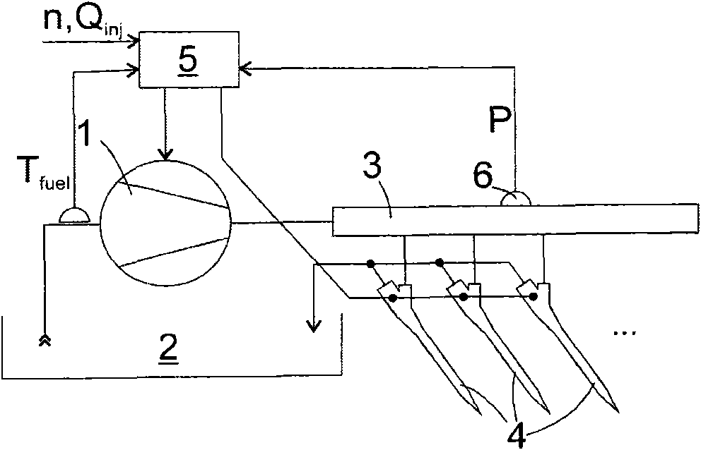
[0071] figure 1 It is a schematic outline of a fuel supply system of a diesel engine to which the present invention is applicable. A fuel pump 1, such as a gear pump or a pump having multiple pistons driven by the same rotating eccentric device, draws fuel from the tank 2 and supplies it to the rail 3 under high pressure. The rail 3 connects any number of injectors 4 to the rail to inject fuel from the rail into a cylinder (not shown) of the diesel engine. Based on rail pressure P and fuel temperature T detected by sensors 6 and 7 at rail 3 fuel , The rotational speed n of the diesel engine and the fuel injection quantity Q to be injected per cylinder per stroke inj (Set by a higher-level controller (not shown)), the electronic controller 5 controls the rotation speed of the pump 1 and the activation time of the ejector 4.

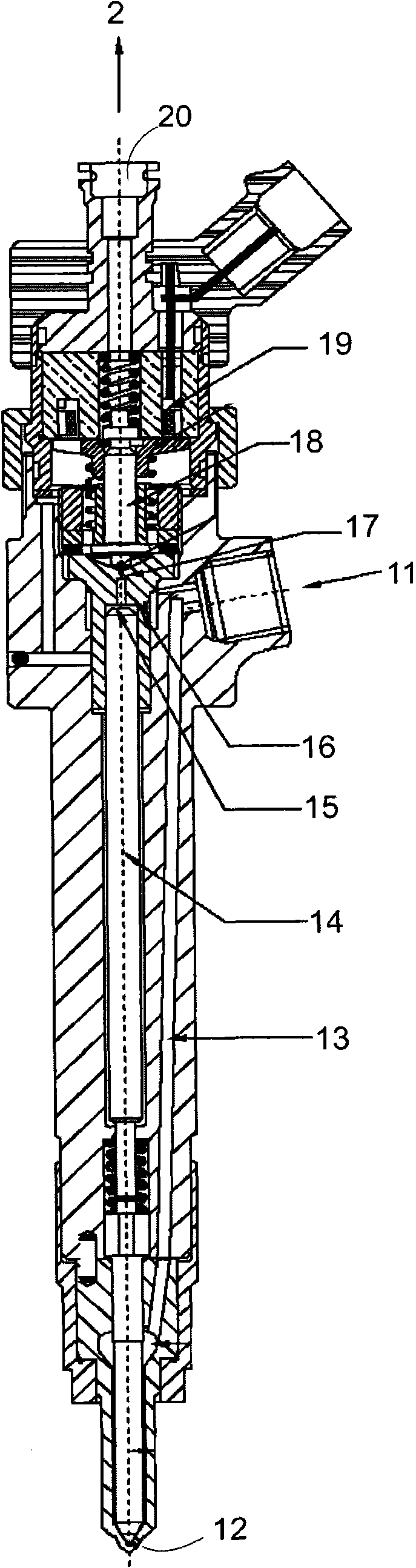
[0072] figure 2 It is a schematic longitudinal section of the ejector 4. The high-pressure fuel inlet 11 (which receives fuel from the rail 3) is connec...


PUM


Abstract

A method for controlling rail pressure in a fuel supply system comprising a fuel pump 1, at least one injector 4 and a rail 3 connecting the injector (4) to the pump (1), comprises the steps of establishing a relationship between rail pressure (P) and a leak rate of the injector (4), estimating a fuel drain rate from the rail based on a fuel injection rate (Qinj), rail pressure (P) and rail pressure / leak rate relationship; estimating a desired intake flow rate of the pump based on fuel drain rate and controlling the pump (1) to operate at a desired intake flow rate.

Description

Technical field [0001] The invention relates to a method for controlling supply rail pressure in a fuel supply system, particularly for diesel engines, and to a device for performing the method. Background technique [0002] Traditionally, the fuel supply system of a diesel engine includes a fuel pump capable of delivering a high output pressure of up to 1600 bar, an injector associated with each cylinder of the engine, and a rail connecting the injector to the pump. The ejector includes an electromagnet (solenoid) or a piezoelectric element to electrically control a pilot valve. The pilot valve controls the flow of fuel to the pressure receiving surface of the valve piston so that the tip of the valve piston is pressed against the nozzles of the injector and blocks these nozzles, or is retracted, allowing fuel to be ejected from the nozzles. Due to this operating principle, only part of the fuel flowing into the injector is actually injected into the cylinder. The fuel used to...

Claims


Application Information

Patent Timeline
Patent Type & Authority Applications(China)
IPC IPC(8): F02D41/38F02M55/02
CPCF02D41/3872F02D2041/142F02D41/3845
Inventor 毛拉·丁提诺文森佐·拉姆皮诺尤金尼奥·皮索尼
Owner GM GLOBAL TECH OPERATIONS LLC
Why Eureka
Try Eureka