Cable gas insulated switchgear (GIS) terminal tester

A terminal test and cable technology, applied in the direction of measuring devices, measuring electricity, measuring electrical variables, etc., can solve the problems such as being unsuitable for the completion inspection of GIS switchyards, many cooperating units, and long operating cycles, and achieves convenient and fast testing. Use conditions, the effect of strong on-site applicability

Active Publication Date: 2012-08-15
WUXI POWER SUPPLY JIANGSU PROVINCE ELECTRIC POWER +1
View PDF0 Cites 0 Cited by
  • Summary
  • Abstract
  • Description
  • Claims
  • Application Information

AI Technical Summary

Problems solved by technology

In the cable completion test in the second case, due to the differences in the structure of the GIS cable switch gas chamber of each GIS equipment manufacturer, the structure in which the cable terminal is directly connected to the arrester and pressure transformer in the GIS gas chamber (without switch knife separation) has been used in recent years. It is very extensive, which leads to the test according to the withstand voltage value of the handover test, and the cable terminal, lightning arrester, and voltage change connecting rod must be removed. After the test is completed, the cable terminal is drawn out and the connecting rod is reinstalled. There are many units and the operation cycle is long
This kind of device in foreign countries is relatively bulky, and it needs to be installed on the upper end of the GIS switch cabinet during the test, requiring the GIS switch station workshop to have a certain height to conduct the test; therefore, this device is not suitable for the completion inspection of the domestic GIS switch station

Method used


Image

  • Cable gas insulated switchgear (GIS) terminal tester
  • Cable gas insulated switchgear (GIS) terminal tester

Examples


Embodiment Construction

[0012] The present invention will be further described below in conjunction with specific drawings and embodiments.

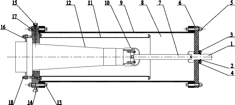
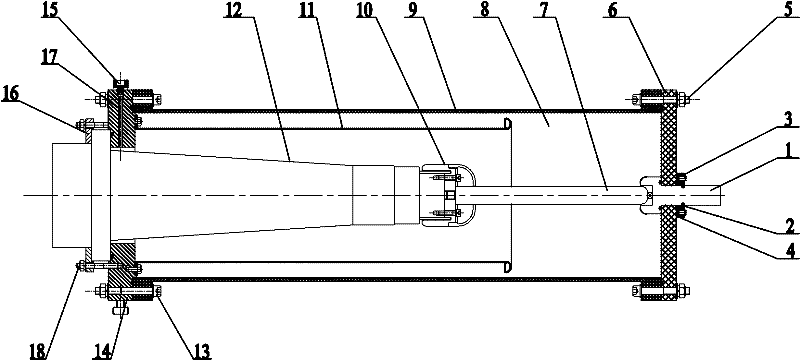
[0013] like figure 1 Shown: the present invention includes outlet rod 1, positioning pin 2, positioning plate 3, flat washer 4, insulating bolt 5, insulating top cover 6, guide rod 7, insulating gas 8, insulating cylinder 9, shielding cover 10, shielding electrode 11. GIS terminal 12, bottom plate fixing bolts 13, bottom plate 14, shell vacuum port 15, snap ring 16, vacuum hole 17 and snap ring fastening bolts 18.

[0014] like figure 1 As shown: one end of the insulating cylinder 9 is provided with a fixedly connected bottom plate 14, the bottom plate 14 matches the shape of the end of the insulating cylinder 9, and the bottom plate 14 is connected to the insulating cylinder 9 through the bottom plate fixing bolts 13. Fixed, the bottom plate fixing bolt 13 is made of metal material. The other end of the insulating cylinder 9 corresponding to the bottom plat...


PUM


Abstract

The invention relates to a cable gas insulated switchgear (GIS) terminal tester which comprises an insulated cylindrical shell, wherein one end of the insulated cylindrical shell is provided with a fixedly connected base plate, and the other end, which corresponds to the arranged base plate, of the insulated cylindrical shell is provided with a fixedly connected insulated top cap; a test cavity is formed among the interior of the insulated cylindrical shell, the insulated top cap and the base plate; a vacuum hole is reserved on the base plate and is communicated with the test cavity; a line-outgoing rod is arranged on the insulated top cap, one end of the line-outgoing rod penetrates through the insulated top cap and then is extended into the insulated cylindrical shell, and the line-outgoing rod is fixedly connected with the insulated top cap; the line-outgoing rod is provided with a guide rod corresponding to the end stretching into the insulated cylindrical shell, and the guide rodis electrically connected with the line-outgoing rod; the insulated cylindrical shell is internally provided with a shielding electrode, and the shape of the insulated electrode is matched with the insulated cylindrical shell; and one end of the insulated electrode is fixed with the base plate. The cable GIS terminal tester is simple and compact in structure, light in weight, strong in on-site adaptability, low in cost and convenient in operation and has safety and reliability.

Description

technical field [0001] The present invention relates to a test device, in particular to a cable GIS terminal test device, in particular to a test device for high-voltage cross-linked cables and corresponding accessories between switching stations with GIS terminals at both ends. Background technique [0002] There are usually two cases for cables using GIS (Gas Insulated Switchgear) terminals: the first case is that one end is a GIS terminal and the other end is an outdoor terminal; the second case is that both ends are GIS terminals. In the first case, when the completion test of the cable is carried out, it can generally be disconnected from the outdoor terminal and the overhead line, and a DC voltage (oil-filled cable) or AC voltage (cross-linked cable) is applied to the outdoor terminal of the cable for the completion test. In the cable completion test in the second case, due to the differences in the structure of the GIS cable switch gas chamber of each GIS equipment m...

Claims


Application Information

Patent Timeline
Patent Type & Authority Patents(China)
IPC IPC(8): G01R31/00G01R31/12
Inventor 顾青何光华张志坚吴寅雄许欣宇罗锋杨东兴谢江虹
Owner WUXI POWER SUPPLY JIANGSU PROVINCE ELECTRIC POWER
Why Eureka
Try Eureka