
A lower formwork for pipe piles and its hoisting system

A technology of pipe piles and spreaders, applied in the directions of molds, transportation and packaging, load hanging elements, etc., can solve problems such as easy decoupling

Active Publication Date: 2016-03-30
ZHEJIANG KNSN PIPE & PILE
View PDF6 Cites 0 Cited by
  • Summary
  • Abstract
  • Description
  • Claims
  • Application Information

AI Technical Summary

Problems solved by technology

[0003] In order to solve the above deficiencies, the present invention provides a pipe pile lower mold and its hoisting system. This system effectively solves the production risk of easy decoupling or side-to-side swing caused by high-strength steel cables when the existing pipe pile mold is hoisted. Simple and effective, it greatly reduces the risk of accidents in the production process of the pipe pile assembly line. At the same time, only one driving operator is required to automatically complete the lifting and unloading of the pipe pile mold, which greatly improves the production efficiency.

Method used


Image

  • A lower formwork for pipe piles and its hoisting system
  • A lower formwork for pipe piles and its hoisting system
  • A lower formwork for pipe piles and its hoisting system

Examples


Embodiment 1

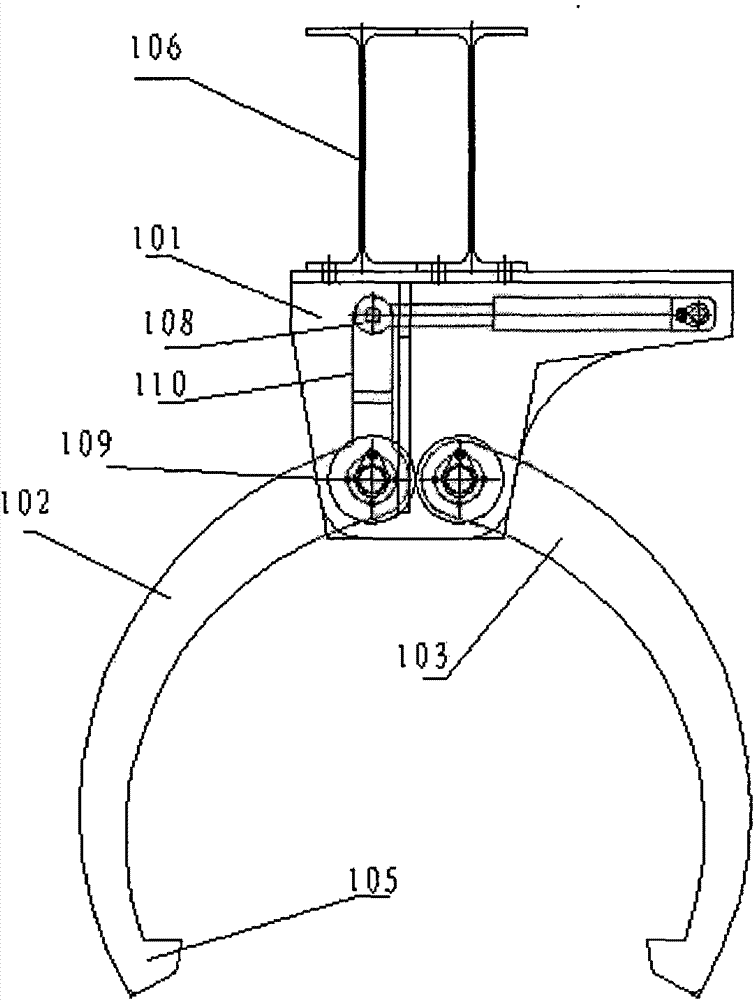
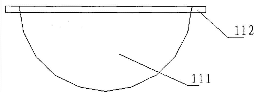
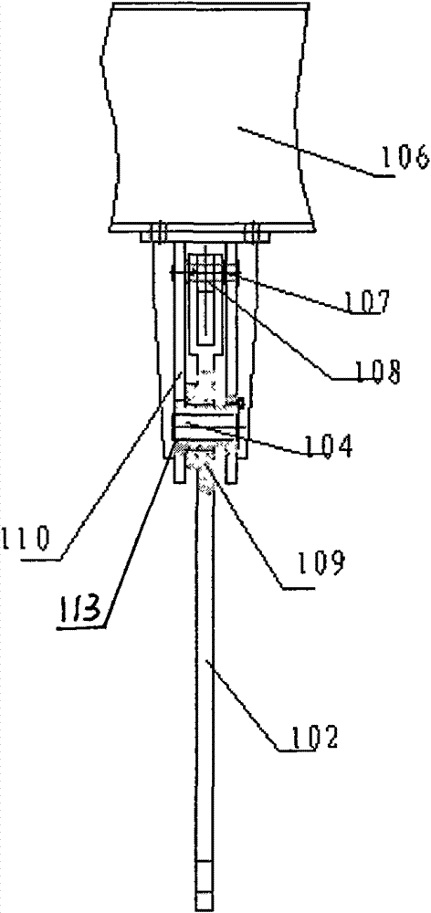
[0017] Embodiment 1, when the staff needs to hoist the lower mold (111) of the pipe pile, the driving vehicle moves to the designated position, the driving control motor works, the motor rotates to drive the upper gear (108) to rotate clockwise, and the middle gear is driven by the chain (110) (113) rotates, middle gear (113) and lower gear (109) coaxially rotate, drives lower gear (109) to rotate, and lower gear (109) rotates the lower gear ( 109) Synchronously rotate in the opposite direction, the lower gears (109) on the left and right sides of the lower end of the bracket (101) rotate, and the left arm (102) and right arm (103) of the spreader connected to it through the pin shaft (104) are opened, and the driving Control and control the hoisting system to descend to the position of the pipe pile lower mold (111), the control system controls the motor to work, the motor rotates to drive the upper gear (108) to rotate counterclockwise, and the chain (110) drives the middle g...

Embodiment 2

[0018] Embodiment 2 After the traffic control hoisting system moves up to the designated position, the traffic control hoisting system descends to the designated position, the traffic control motor works, the motor rotates to drive the upper gear (108) to rotate clockwise, and the chain (110) drives the middle gear (113 ) rotates, the middle gear (113) and the lower gear (109) rotate coaxially, driving the lower gear (109) to rotate, and the rotation of the lower gear (109) drives the lower gear (109) on the right side of the lower end of the bracket (101) engaged with it Synchronously rotate in the opposite direction, the lower gears (109) on the left and right sides of the lower end of the bracket (101) rotate, and the left arm of the spreader (102) and the right arm of the spreader (103) connected to it through the pin shaft (104) are opened, and the pipe pile Lower mold (111) is unloaded.


PUM


Abstract

The invention discloses a pipe pile lower die and a lifting system thereof, which consist of a lifting appliance system and a die system, wherein the lifting appliance system consists of a bracket, a lifting appliance left arm, a lifting appliance right arm, a pin shaft, a lifting hook, a hanging bracket, an upper gear pin shaft, an upper gear, a lower gear, a middle gear and a chain; the die system consists of the pipe pile lower die and a lower die lug boss; the lifting appliance system is connected at the lower end of a crane; and a motor drives a pinion to work and is controlled by a crane control system. The invention has the advantages that: the system effectively solves the problems that the traditional pipe pile dies are easily unhooked during lifting or result in production risk due to movement from side to side of a high-strength steel cable, simultaneously the pipe pile lower die can be automatically lifted and unloaded by only one crane operator, and the production efficiency is three times that of the traditional lifting system.

Description

【Technical field】 [0001] The invention relates to the technical field of a construction machinery device, in particular to the technical field of a pipe pile lower die and its hoisting system. 【Background technique】 [0002] As we all know, with the construction needs of large-scale projects such as modern urban real estate, bridges, and ports, the application fields of pipe piles are becoming wider and wider. From the introduction of the first production line from Japan in the 1970s, my country has developed a variety of pipe pile production lines by itself, and a very important part of the pipe pile production line is the hoisting of pipe piles and molds, because pipe piles are heavy. Generally, the pipe pile or mold can be moved well by using the crane and the spreader together. The traditional pipe pile hoisting equipment generally pulls several high-strength steel cables under the crane, and a hook is connected to the lower end of the steel cable. hole and then lift to...

Claims


Application Information

Patent Timeline
Patent Type & Authority Patents(China)
IPC IPC(8): B28B21/76B66C1/28
Inventor 张建华
Owner ZHEJIANG KNSN PIPE & PILE
Learn More