
Novel fluorescent lamp electrode and installation method thereof

A fluorescent lamp and electrode technology, which is applied in the manufacture of electrode components, circuits, discharge lamps, etc., can solve the problems of insignificant quality of fluorescent lamps, short lifespan of lamp blackheads, and few application manufacturers, so as to reduce blackening phenomenon and save energy. The effect is remarkable and the market capacity is large

Inactive Publication Date: 2011-03-30
黄嘉宾
View PDF0 Cites 1 Cited by
  • Summary
  • Abstract
  • Description
  • Claims
  • Application Information

AI Technical Summary

Problems solved by technology

[0002] In the prior art, after the fluorescent lamp is used for a period of time, the two ends of the lamp tube will be blackened. The main reason is that the electron emitters will scatter and attach to the inner wall of the lamp tube when the lamp is turned on. There is a view that the life of the black head of the lamp tube is not long. In order to solve the above problems, some lamp manufacturers install metal shielding rings at both ends of the fluorescent lamp to prevent the blackening of the two ends of the lamp tube, and at the same time increase the area of ​​the anode and reduce the The total energy input to the oxide-coated cathode avoids overheating of the cathode and has achieved certain results, but it has little significance in improving the quality of fluorescent lamps, so there are few manufacturers applying it

Method used


Image

  • Novel fluorescent lamp electrode and installation method thereof
  • Novel fluorescent lamp electrode and installation method thereof
  • Novel fluorescent lamp electrode and installation method thereof

Examples


Embodiment Construction

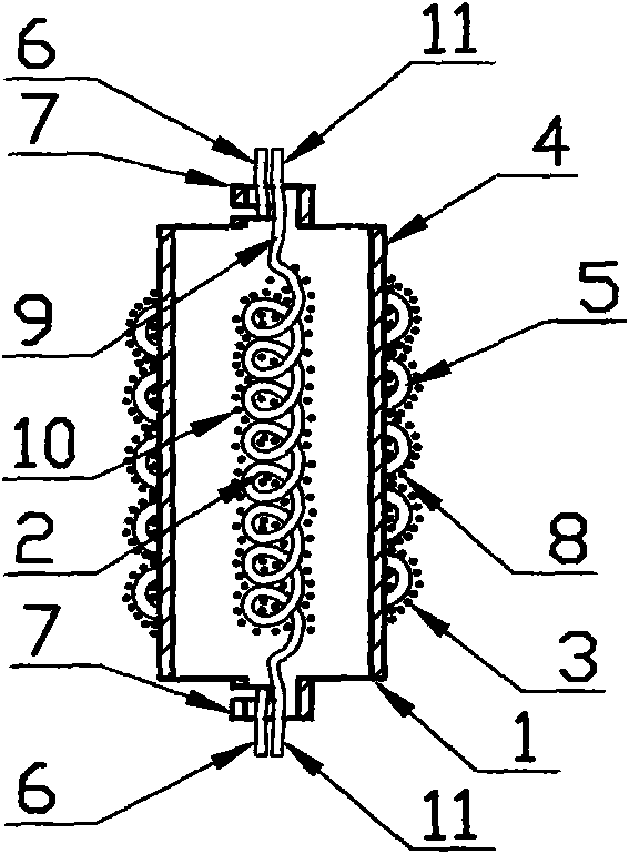
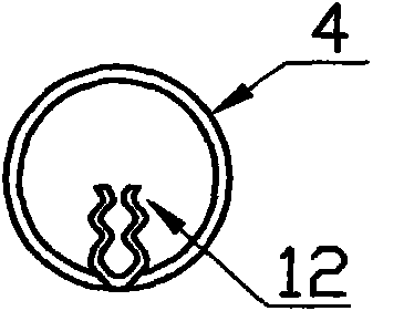
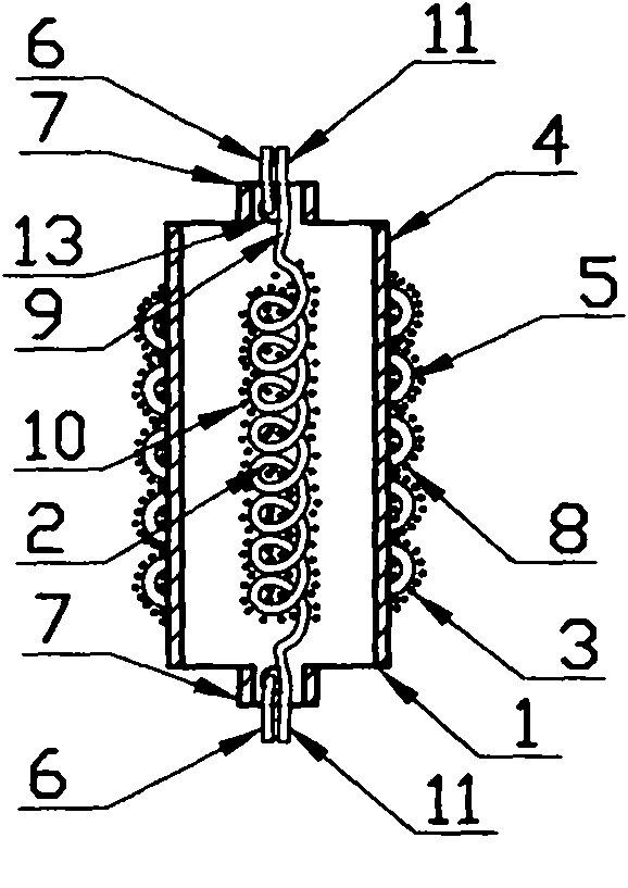
[0020] Such as figure 1 Shown is a schematic diagram of the structure of the new electrode of the present invention. The new electrode 1 of the fluorescent lamp is composed of a central electrode 2 and a screen electrode 3. The screen electrode 3 is processed into a hollow molybdenum tube 4 by using a molybdenum sheet, and a tungsten wire or a filament 5 is wound around the hollow molybdenum tube. 4, the lead wires 6 at both ends of the tungsten wire or filament 5 are respectively connected to the pins 7 at both ends of the hollow molybdenum tube, and the tungsten wire or filament 5 on the hollow molybdenum tube 4 is coated with cathode material 8 and sintered at high temperature; the central electrode 2 Composed of filament 9, the filament 9 coated with cathode material 10 is sintered at high temperature, placed in the inner hole of the hollow molybdenum tube 4 of the screen electrode 3, and the leads 11 at both ends are respectively connected to the pins 7 at both ends of the...


PUM


Abstract

The invention relates to a novel fluorescent lamp electrode and an installation method thereof. The novel fluorescent lamp electrode consists of a central electrode and a shielding screen electrode, wherein the shielding screen electrode is processed into a hollow molybdenum tube with a molybdenum sheet, a tungsten filament or a lamp filament is wound on the hollow molybdenum tube and coated with a cathode material, and the central electrode is composed of lamp filaments, and is arranged in an inner hole of the hollow molybdenum tube after being coated with the cathode material, lead wires on two ends of the central electrode and the shielding screen electrode are respectively connected to pins on two ends of the hollow molybdenum tube, and the resistance value of the shielding screen electrode is set to be larger than that of the central electrode. Electrode supports of core columns are arranged respectively in a way that one is long, and the other one is short, pins on two ends of the novel electrodes are respectively connected with the longer and the shorter core column electrode supports, thus enabling the novel electrode to be erected in the core column. By adopting the novel electrode in the fluorescent lamp, not only is the blackening phenomenon on two ends of the fluorescent lamp reduced, but also the service life of a tube is doubled.

Description

technical field [0001] The invention relates to a gas discharge lamp, in particular to a new type electrode for a fluorescent lamp composed of a center electrode and a screen electrode, and also relates to a method for installing the electrode of the fluorescent lamp. Background technique [0002] In the prior art, after the fluorescent lamp is used for a period of time, the two ends of the lamp tube will be blackened. The main reason is that the electron emitters will be scattered and attached to the inner wall of the lamp tube when the lamp is turned on. There is a view that the life of the black head of the lamp tube is not long. In order to solve the above problems, some lamp manufacturers install metal shielding rings at both ends of the fluorescent lamp to prevent the blackening of the two ends of the lamp tube, and at the same time increase the area of ​​the anode and reduce the The total energy input to the oxide-coated cathode avoids overheating of the cathode and h...

Claims


Application Information

Patent Timeline
Patent Type & Authority Applications(China)
IPC IPC(8): H01J61/067H01J61/10H01J9/18
Inventor 黄嘉宾
Owner 黄嘉宾
Learn More