Fixed device of horizontal blocking rod of combined bedstead

A fixing device and cross block technology, applied in the direction of bed frame, other seating furniture, home appliances, etc., can solve the problem of affecting the quality of the embedded cross bar, the embedded cross bar is not easy to process, and the two ends of the body are cracked, etc. problems, to achieve the effect of easy mold opening and manufacturing, improved support capacity, and reduced weight

Active Publication Date: 2011-03-23
HOUSE & HOME CO LTD
View PDF0 Cites 1 Cited by
  • Summary
  • Abstract
  • Description
  • Claims
  • Application Information

AI Technical Summary

Problems solved by technology

Due to the limitation of the upper corners of the body, it is difficult to form an ideal triangle on the other two sides during extrusion to ensure smooth extrusion of the body; a large pressure is required and the two ends of the body are prone to cracking, which affects the embedded crosspiece rod quality
Embedded cross bar is not easy to process

Method used


Image

  • Fixed device of horizontal blocking rod of combined bedstead
  • Fixed device of horizontal blocking rod of combined bedstead
  • Fixed device of horizontal blocking rod of combined bedstead

Examples


Embodiment 1

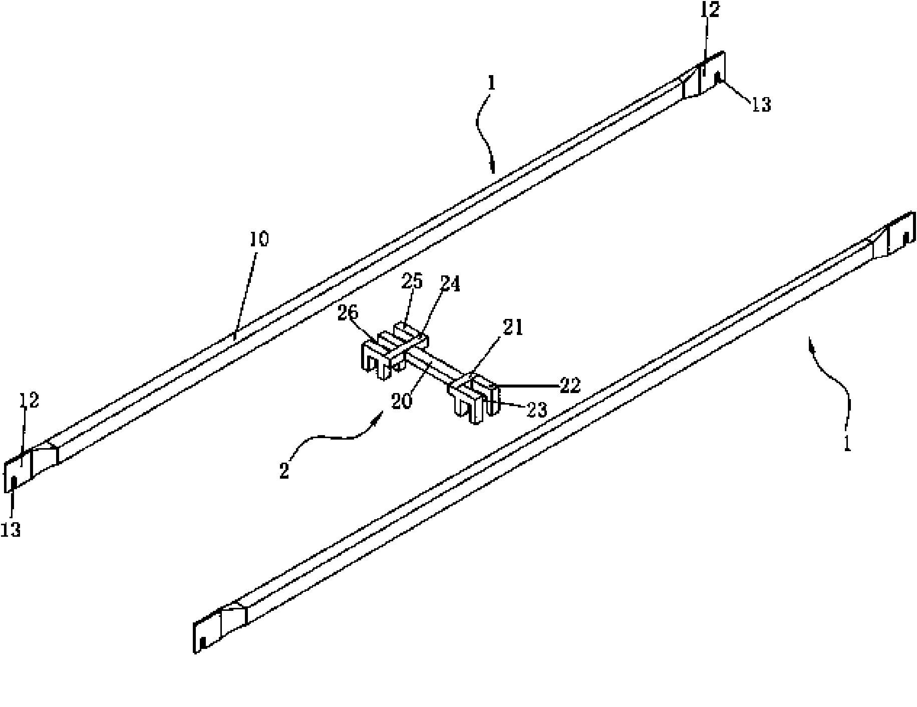
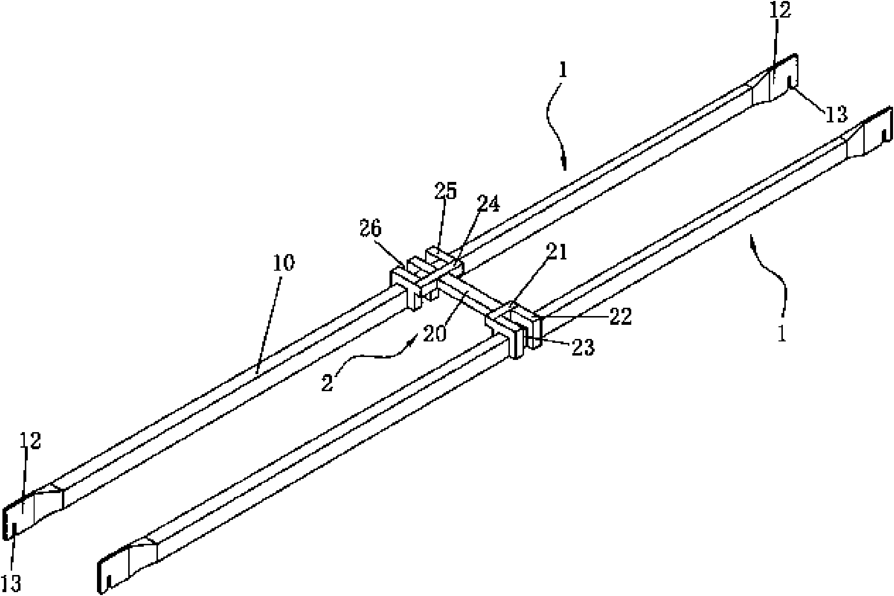
[0021] An embodiment of the fixing device of the present invention's combined bed frame cross bar, see figure 1 , is a clip 2 for fixing the distance between adjacent cross bars 1 .

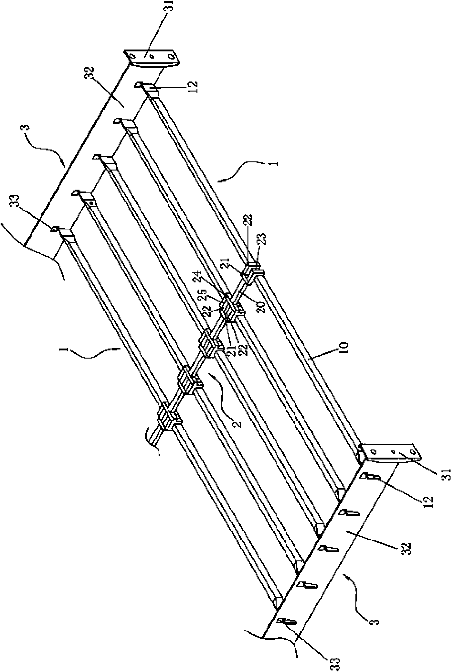
[0022] The cross bar 1 applicable to this embodiment adopts a metal tube with a rectangular cross-section, which is cut into a tubular body 10 according to the required length. Both ends of the main body 10 are respectively extruded into sheet-shaped clamping portions 12 , and slots 13 are respectively opened on the lower edges of the two clamping portions 12 .

[0023] The middle part of the snap connector 2 is a rod 20 . The first end 21 of the rod 20 is provided with two claws 22 side by side, leaving a space 23 between the two claws 22; the second end 24 of the rod 20 is provided with three claws 25 side by side, and two adjacent claws Spaces 26 are left between the claws 25 . The claws 22 on the first end 21 of the snap connector 2 and the claws 25 on the second end 25 are arranged in a s...

Embodiment 2

[0037] The second embodiment of the fixing device for the cross bar of the combined bed frame of the present invention is suitable for the embedded cross bar which is easier to process than the rectangular section embedded cross bar. The three-dimensional structure of the snap connector 200 in this embodiment and the two crossbars 100 connected to it is as follows: Figure 8 shown.

[0038] The cross bar 100 applicable to this embodiment adopts a metal round tube, which is cut into a tubular body 1000 according to the required length. A process hole 1100 is respectively provided near two ends of the body 1000 . Two ends of the main body 1000 are located outside the corresponding process holes 1100 and are respectively extruded into sheet-shaped clamping parts 1200 , and card slots 1300 are respectively opened on the lower edges of the two clamping parts 1200 .

[0039] A rod 2000 is formed in the middle of the snap connector 200 . The first end 2100 of the rod 2000 is provi...


PUM


Abstract

The invention discloses a fixed device of a horizontal blocking rod of a combined bedstead, relating to a component of the combined bedstead. The fixed device of the horizontal blocking rod of the combined bedstead is connected between the middle parts of the two adjacent horizontal blocking rods, wherein the two ends of the device are respectively provided with clampers for clamping claws corresponding to the horizontal blocking rods; at least two claws are arranged in parallel at the two ends of the clamper, or the number of the claws at one end of the clamper is one more than that of the claws at the other end; and the claws at the two ends of the clamper are crossly arranged and the width of each claw on the clamper is slightly less than the space between the two adjacent claws. Particularly, the body of each horizontal blocking rod is a round pipe, and the cross section of the claws on each clamper is in a C shape which is matched with the diameter of the horizontal blocking rod bodies, therefore, the problem of difficult assembly of the combined bedstead is solved.

Description

technical field [0001] The invention relates to a part of a combined bed frame. Background technique [0002] The existing combined bed frame has two oppositely arranged headboards, and a longitudinal beam is respectively installed on the left and right sides of the two headboards to form a rectangular frame. A plurality of crossbars are evenly arranged on each longitudinal beam along the length direction to control the distance between the two longitudinal beams and support the mattress. Existing cross bars are all made of rectangular section metal tubes. The two ends of each cross bar are respectively fixed on the longitudinal beam on the same side, and are stably fixed with the longitudinal beam. For safety requirements, in order to prevent the user from inserting his or her feet between two adjacent cross bars when standing on the bed, causing the cross bars to deform and jam his or her feet, resulting in injury; A through hole is drilled in the middle of each crossba...

Claims


Application Information

Patent Timeline
Patent Type & Authority Applications(China)
IPC IPC(8): A47C19/02
Inventor 陈旭升
Owner HOUSE & HOME CO LTD
Why Eureka
Try Eureka