
Bioreactor

A bioreactor and container technology, applied in the direction of sustainable biological treatment, biological water/sewage treatment, chemical instruments and methods, etc., can solve the problem of low gas-liquid-solid separation efficiency, improve biological treatment reaction efficiency, prevent gas Flow into the discharge pipe and the effect of improving the efficiency of gas-liquid-solid separation

Inactive Publication Date: 2011-02-23
KURITA WATER INDUSTRIES LTD
View PDF3 Cites 2 Cited by
  • Summary
  • Abstract
  • Description
  • Claims
  • Application Information

AI Technical Summary

Problems solved by technology

[0007] The gas-liquid-solid separator used in the Japanese Patent Laid-Open Publication No. 10-165980 and Japanese Patent Publication No. 7-507233 has a simple structure and low gas-liquid-solid separation efficiency

Method used


Image

  • Bioreactor
  • Bioreactor
  • Bioreactor

Examples


Embodiment Construction

[0044] Hereinafter, embodiments will be described with reference to the drawings.

[0045] [Bioreactor in which the solid component discharge pipe is inclined as a whole]

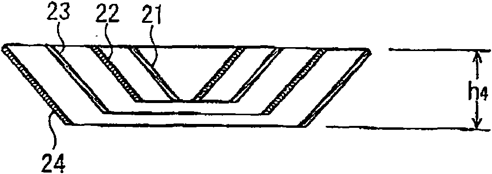
[0046] figure 1 It is a longitudinal sectional view of a bioreactor in which the solid component discharge pipe is inclined as a whole, figure 2 (a) is figure 1 The enlarged view of the upper part of the bioreactor in figure 2 (b) is a plan view of the gas-liquid-solid separator, image 3 It is the longitudinal section view of the baffle. also, figure 2 (a) display edge figure 2 (b) A-A line section. Figure 4 (a) is an enlarged view of the upper part of the bioreactor of another embodiment, Figure 4 (b) is Figure 4 (a) Perspective view of the gas-liquid-solid separator in (a).

[0047] Figure 1 to Figure 3 In the shown embodiment, the container 1 is cylindrical, and raw water (raw water) is supplied from the raw water pipeline 2 to the distributor (distributor) 3 in the lower part of the co...


PUM


Abstract

The invention provides a biological reactor having a high efficiency of gas-liquid-solid separation and hence capable of enhancing the biological reaction efficiency in a vessel. The area of the vessel 1 from around the middle part to the bottom part forms a biological reaction zone S where sludge floats. Raw water undergoes an anaerobic biological treatment in the biological reaction zone S and is introduced into a gas-liquid-solid separator 4 installed in the upper part of the vessel 1 for the gas-liquid-solid separation. The treated water via the gas-liquid-solid separation process is discharged out of the vessel 1 through a treated water discharging conduit 6. The solid matter settles in the gas-liquid-solid separator 4 and is returned to the biological treatment zone S in the vessel 1 through a solid matter discharging conduit 7. The separator 4 is internally installed with baffles 21 to 24, each of which is made of an annular sheet in a tapered form whose diameter becomes smaller toward the lower portion. Each baffle 21 to 24 is disposed concentrically with a space in between.

Description

[0001] This application is a divisional application of the invention patent application named "bioreactor" with application number 200610152871.0, and the filing date of the original application is November 06, 2006. technical field [0002] The present invention relates to a bioreactor suitable for biological treatment of wastewater, and in particular to a bioreactor with a gas-liquid-solid separation chamber on the top of a container for biological reactions. Background technique [0003] For a long time, UASB (Upflow Anaerobic Sludge Blanket, upflow anaerobic sludge bed) or EGSB (Expanded Granular Sludge Bed, granular sludge expanded bed) biological treatment device has been widely used in the biological treatment of organic drainage (biotreatment ). By performing these UASB and EGSB treatments, the organic substances in the wastewater are converted into methane and CO through anaerobic biological treatment. 2 gas. Therefore, the biologically treated water will contain ...

Claims


Application Information

Patent Timeline
Patent Type & Authority Applications(China)
IPC IPC(8): C02F9/14
CPCC02F3/284C02F3/2866C02F2201/002Y02W10/10
Inventor 葛艾鲁拉吉普三轮聪志
Owner KURITA WATER INDUSTRIES LTD
Learn More