
Drive circuit for reducing motor

A deceleration motor and drive circuit technology, applied in the direction of motor generator/starter, single multi-phase induction motor starter, etc., can solve the problems of laborious, single function, inconvenient, etc., achieve automatic forward and reverse rotation function, realize The effect of forward and reverse rotation function

Inactive Publication Date: 2011-02-16
SUZHOU HEXINMEI ELECTRONICS SCI & TECH CO LTD
View PDF4 Cites 1 Cited by
  • Summary
  • Abstract
  • Description
  • Claims
  • Application Information

AI Technical Summary

Problems solved by technology

[0003] However, the rotation of the auxiliary dining table is often done manually, which is not only inconvenient, but also laborious in some cases.
Therefore, a developer has developed a drive circuit for a reducer, which drives the reducer to rotate, and the rotation of the reducer drives the rotation of the auxiliary dining table installed on the reducer to realize the function of the electric rotating table. However, the existing electric rotating table, The function is relatively single, and it can only rotate in one direction, which is inconvenient in the actual application process

Method used


Image

  • Drive circuit for reducing motor
  • Drive circuit for reducing motor

Examples


Embodiment Construction

[0023] The technical implementation process of the present invention will be further described below in conjunction with the accompanying drawings and embodiments.

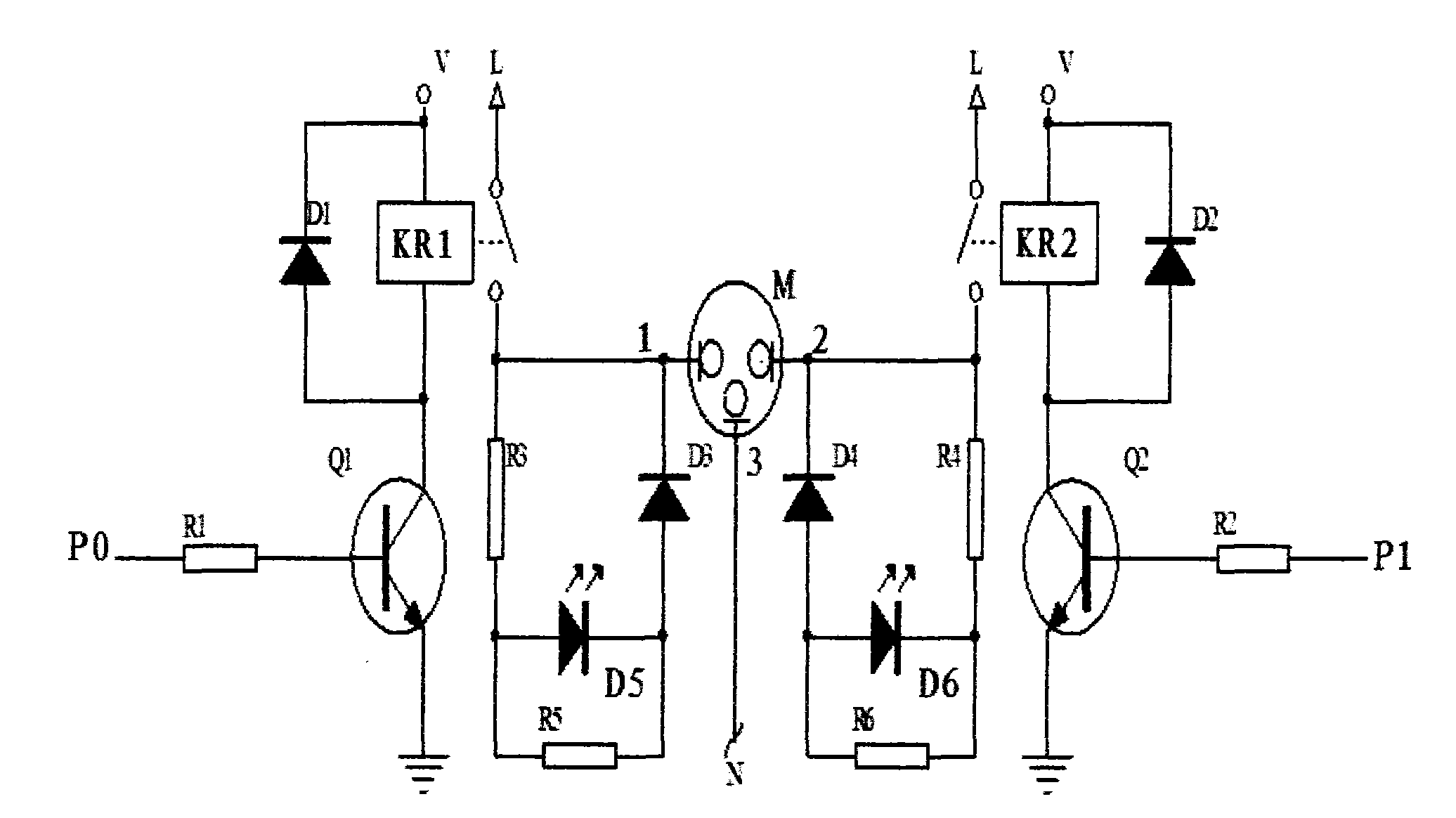
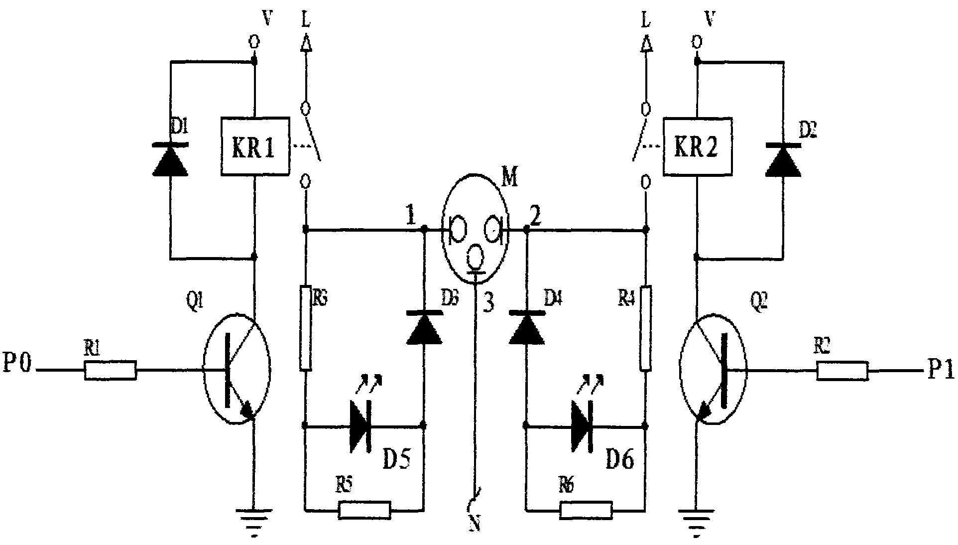
[0024] see figure 1 As shown, a geared motor drive circuit includes a geared motor M, the third input terminal 3 of the geared motor M is connected to the neutral line N, and the first input terminal 1 of the geared motor M is connected to the output of the trigger KR1 One end of the loop, the other end of the output loop of the flip-flop KR1 is connected to the fire line L, one end of the input loop of the flip-flop KR1 is connected to a power supply V, and the other end is connected to the collector of the triode Q1, the The emitter of the triode Q1 is grounded, and the base is connected to the output terminal P0 of a control chip through the resistor R1; the second input terminal 2 of the deceleration motor M is connected to one end of the output circuit of the trigger KR2, and the output terminal of the trigge...


PUM


Abstract

The invention discloses a drive circuit for a reducing motor, which comprises the reducing motor M, wherein, a third input terminal of the reducing motor M is connected to a null line N, a first input terminal of the reducing motor M is connected on one end of an output circuit of a trigger KR1, and the other end of the output circuit of the trigger KR1 is connected to a live line L; one end of an input circuit of the trigger KR1 is connected to a power supply V, and the other end thereof is connected to the collecting electrode of a triode Q1; the emitting electrode of the triode Q1 is grounded, and the base electrode thereof is connected on an output terminal P0 of a control chip through a resistor R1; and a second input terminal of the reducing motor M is connected with the same circuit as the first input terminal of the reducing motor M. The drive circuit of the invention can simply and effectively realize positive and reverse rotation functions of the reducing motor.

Description

technical field [0001] The invention relates to a circuit applied to a geared motor, in particular to a drive circuit of a geared motor. Background technique [0002] A rotatable turntable is often set on the existing dining table, and the turntable is used as an auxiliary table to place dishes containing dishes. By rotating the auxiliary table, diners on different seats can easily get them The delicacies you want to taste. [0003] However, the rotation of the auxiliary dining table is often done manually, which is not only inconvenient, but also relatively laborious in some cases. Therefore, a developer has developed a drive circuit for a reducer, which drives the reducer to rotate, and the rotation of the reducer drives the rotation of the auxiliary dining table installed on the reducer to realize the function of the electric rotating table. However, the existing electric rotating table, The function is relatively single, and it can only rotate in one direction, which i...

Claims


Application Information

Patent Timeline
Patent Type & Authority Applications(China)
IPC IPC(8): H02P1/40
Inventor 胡国良魏王江
Owner SUZHOU HEXINMEI ELECTRONICS SCI & TECH CO LTD
Learn More