
Electrical machine comprising a rotor, and method for operating said electrical machine

A rotor and running technology, applied in the field of motors with rotors, can solve problems such as motor interference and noise, and achieve the effect of improving the scheme.

Inactive Publication Date: 2011-02-09
ROBERT BOSCH GMBH
View PDF9 Cites 2 Cited by
  • Summary
  • Abstract
  • Description
  • Claims
  • Application Information

AI Technical Summary

Problems solved by technology

This torque fluctuation also leads to the formation of disturbing noise of the motor

Method used


Image

  • Electrical machine comprising a rotor, and method for operating said electrical machine
  • Electrical machine comprising a rotor, and method for operating said electrical machine
  • Electrical machine comprising a rotor, and method for operating said electrical machine

Examples


Embodiment Construction

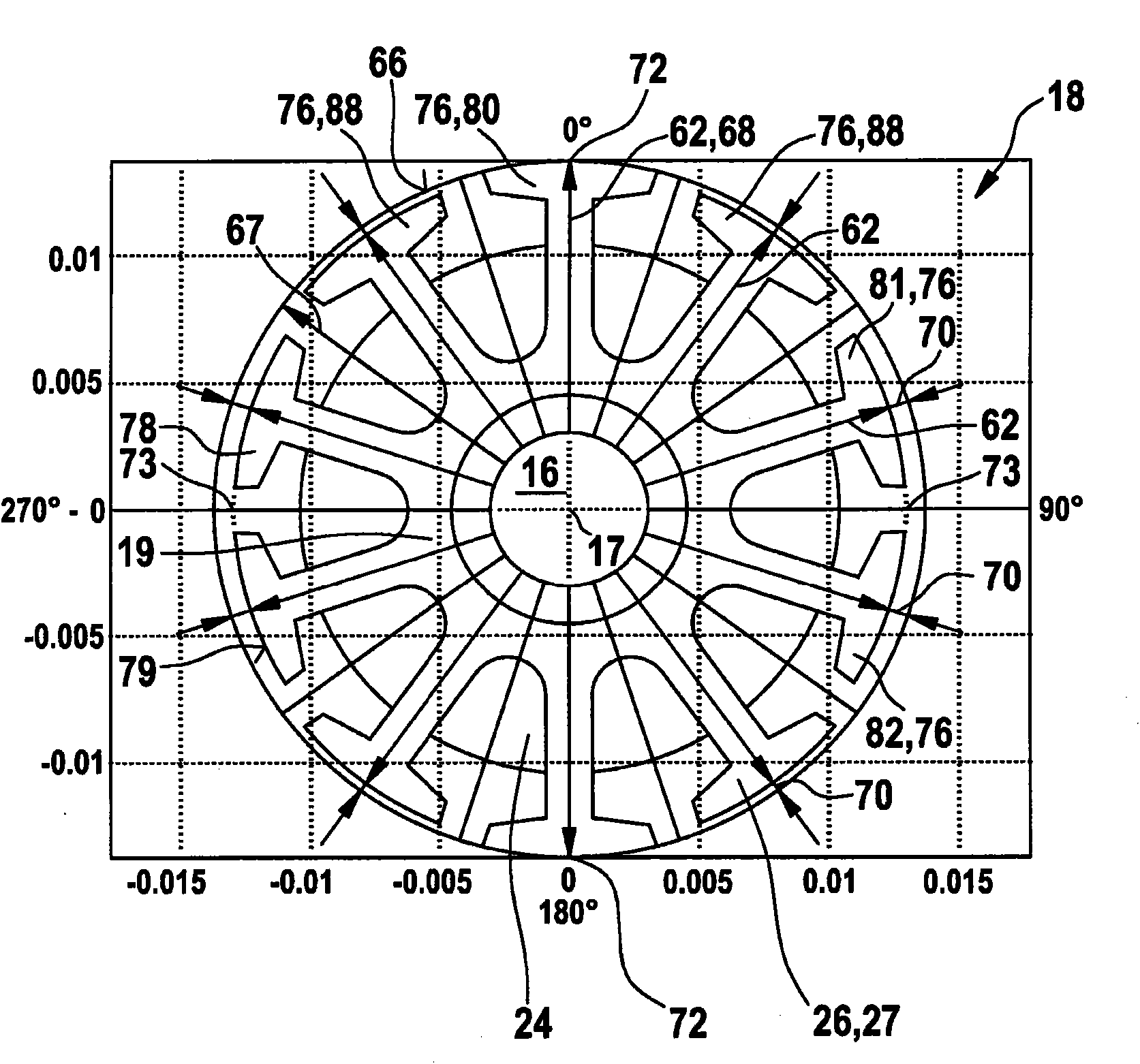
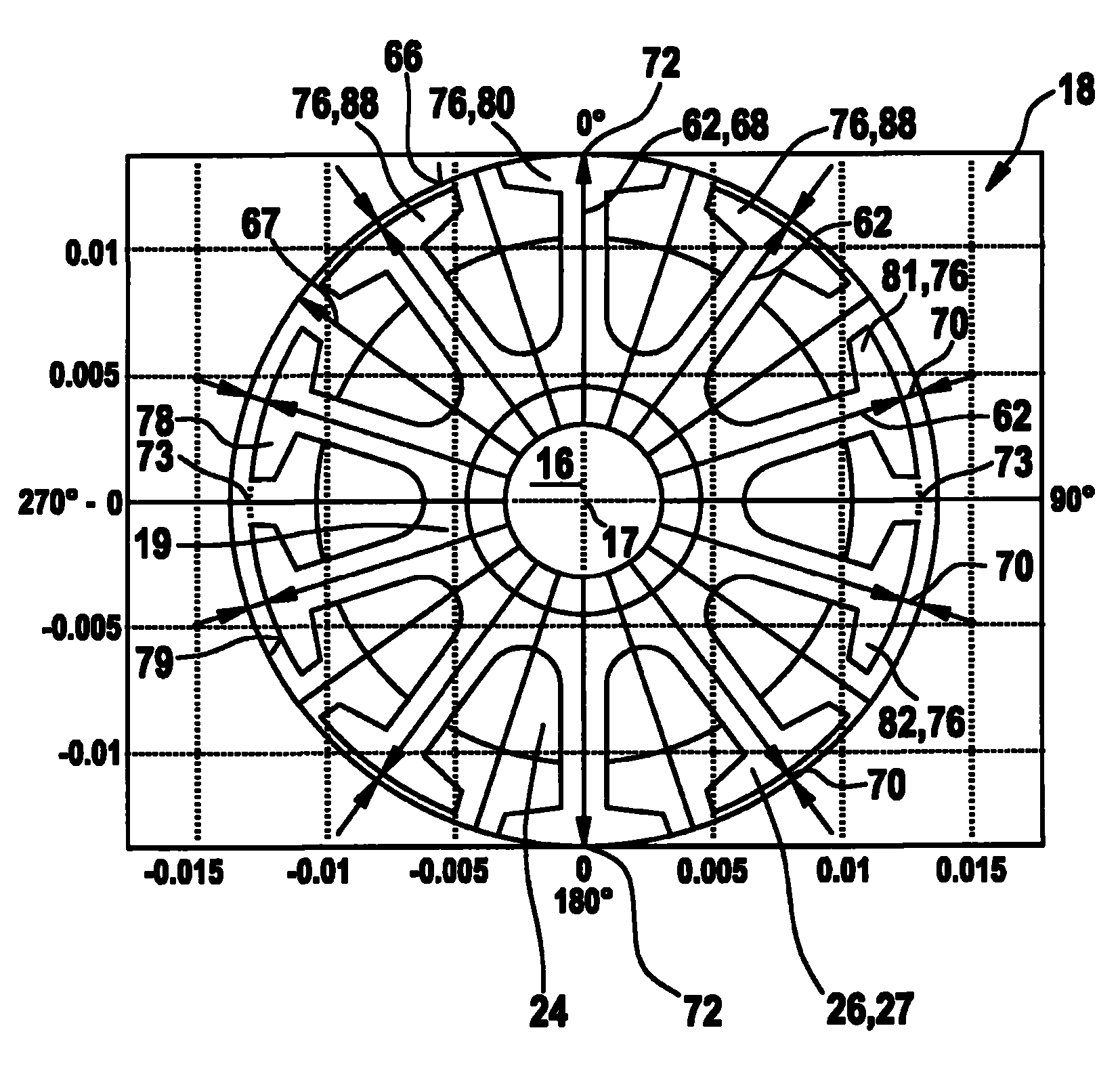
[0020] exist figure 1 A rotor 18 of an electric machine 12 , which is designed, for example, as a DC motor 14 , is shown in . The rotor 18 has a rotor shaft 16 , on which an armature 19 is arranged in a rotationally fixed manner, which is designed, for example, as a lamination pack 26 consisting of individual laminations 27 joined axially together. The rotor 18 has a radius 62 which extends from the axis 17 of the rotor shaft 16 to the outer circumferential surface 64 of the rotor 18 . exist figure 1 A circle 66 is depicted in an auxiliary manner, which has a radius 67 which corresponds to the maximum radius 68 of the rotor 18 . The radius 62 is not constant over the circumference of the rotor 18 , but varies over the circumference, so that a varying length difference 70 of the radius 62 is obtained. The variation of the length difference 70 is preferably sinusoidal or cosine-shaped over the circumference of the rotor 18 . In the example shown, a maximum value 72 of the ra...


PUM


Abstract

The invention relates to an electrical machine (12), especially for power-adjusting a mobile part in a motor vehicle, and to a method for operating said machine. The electrical machine according to the invention comprises a stator (34) and a rotor (18) having a radius (62), said radius (62) varying over the circumference of the rotor (18).

Description

technical field [0001] The invention relates to an electric machine with a rotor and a method for operating the electric machine according to the preambles of the independent claims. Background technique [0002] EP 0 917 755 B1 discloses a commutation arrangement for a direct-current motor, in which the brushes bear against the contact surfaces of the commutator laminations. In this case, the electronics detect the frequency of fluctuations in the motor current, from which the magnitude of the rotational speed of the electric motor is determined. In order to obtain reliable rotational speed information, the edges of the commutator laminations are at a certain angle relative to the longitudinal axis of the commutator or the brush edges. Fabrication of such rectifiers is cumbersome and cannot produce fluctuating frequencies smaller than the slot frequency. [0003] In such electric motors, the AC part of the current signal is evaluated for the detection of the rotational sp...

Claims


Application Information

Patent Timeline
Patent Type & Authority Applications(China)
IPC IPC(8): H02K23/40H02K23/30
CPCH02K23/66H02K23/30H02K23/40
Inventor T·法贝尔G·罗斯
Owner ROBERT BOSCH GMBH
Learn More