
Method, system and user terminal for measuring and triggering measurement report based on reporting set

A measurement report and measurement control technology, applied in electrical components, wireless communication, etc., can solve the problems of insufficient wireless signal, degraded wireless environment quality, and low wireless link level value.

Inactive Publication Date: 2015-08-12
深圳市恒程汇文化科技有限公司
View PDF3 Cites 0 Cited by
  • Summary
  • Abstract
  • Description
  • Claims
  • Application Information

AI Technical Summary

Problems solved by technology

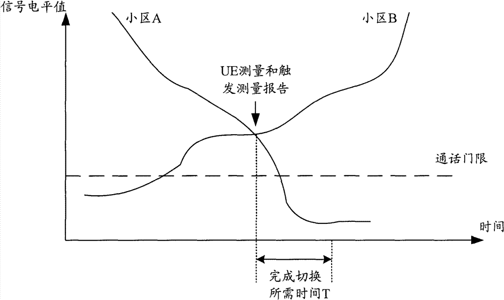
[0004] However, since the UE obtains the measurement result, triggers the measurement report, and the RNC receives the measurement report, decides the handover, and the RNC notifies the UE to perform the handover, it takes a certain amount of time to complete this series of processes. During this period, if the wireless environment quality deteriorates rapidly, then The UE will not be able to complete the normal handover process due to insufficient wireless signal, which will affect the call quality
like figure 2 As shown, the UE has not had time to complete the handover, and the level value of its wireless link is too low, resulting in call drop
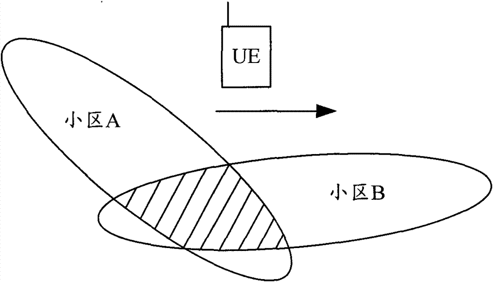
Therefore, there is a need to improve the existing technology in some realistic scenarios. A typical realistic scenario is: for example, a UE moving at high speed along a railway needs to perform multiple handovers between different cells. Since the UE The wireless environment in which you live often experiences severe time-varying, therefore, the quality of the wireless environment is rapidly degraded, which affects the call quality

Method used


Image

  • Method, system and user terminal for measuring and triggering measurement report based on reporting set
  • Method, system and user terminal for measuring and triggering measurement report based on reporting set
  • Method, system and user terminal for measuring and triggering measurement report based on reporting set

Examples


Embodiment 1

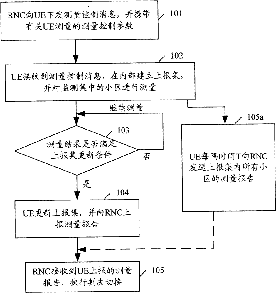
[0126] Embodiment 1: When the reporting set is updated, the measurement report is reported immediately. Such as Figure 4 As shown, in this embodiment, the information interaction between RNC and UE includes the following steps:

[0127] Step 201, the RNC sends a measurement control message to the UE.

[0128] Here, the measurement control message contains the following parameter items: n value, neighbor cell list, the measurement parameter is the RSCP value on the CCPCH channel of the cell, and the trigger condition for reporting the measurement report is to report when the reporting set is updated.

[0129] Step 202, after receiving the control message, the UE establishes a reporting set.

[0130] Here, the UE selects the current serving cell and n-1 neighboring cells with the best received signal quality to establish a reporting set.

[0131] Step 203, the UE keeps measuring the cells in the monitoring set.

[0132] Step 204. When the UE finds that the signal quality of...

Embodiment 2

[0137] Embodiment 2: The situation of periodically reporting measurement reports. In this embodiment, the trigger condition for reporting the measurement report in the measurement control message delivered by the RNC to the UE is periodic reporting, and the rest of the options are the same as those in Embodiment 1. Such as Figure 5 As shown, in this embodiment, the information interaction between RNC and UE includes the following steps:

[0138] Step 301, the RNC sends a measurement control message to the UE.

[0139] Here, the measurement control message contains the following parameter items: n value, neighbor cell list, the measurement parameter is the RSCP value on the CCPCH channel of the cell, the trigger condition for reporting the measurement report is periodic reporting, and the period is T.

[0140] Step 302, after receiving the control message, the UE establishes a reporting set.

[0141] Here, the UE selects the current serving cell and n-1 neighboring cells wi...

Embodiment 3

[0151] Embodiment 3: When the reporting set is updated, the measurement report is reported immediately, and the trigger condition of the reporting set update is corrected through the hysteresis parameter. There is no additional parameter in the measurement control message sent by the RNC in the above two embodiments. This embodiment illustrates the UE measurement with the hysteresis parameter option and the situation of triggering and reporting the measurement report, including the following steps:

[0152] Step 401, the RNC sends the measurement control message to the UE with the following parameter items: n value, adjacent cell list, the measurement parameter is the RSCP value on the CCPCH channel of the cell, and the trigger condition for reporting the measurement report is to report when the report set is updated, At the same time with a hysteresis parameter (Hyst).

[0153] Step 402: After receiving this control message, the UE selects the current serving cell and n-1 nei...


PUM


Abstract

The invention discloses a report set measurement and trigger measurement report based method. The method comprises the following step of: after user equipment (UE) receives a measurement control parameter from a network element (NE) of a network side, establishing a report set according to the measurement control parameter and measuring a cell in a monitoring set. The invention also discloses a report set measurement and trigger measurement report based system which comprises a report set establishing unit and a measuring unit, wherein the report set establishing unit is used for establishing the report set according to the measurement control parameter, and the measuring unit is used for measuring the cell in the monitoring set according to the measurement control parameter. The invention also discloses UE applying the method, which comprises a report set establishing unit and a measuring unit, wherein the report establishing unit is used for establishing the report set according to the measurement control parameter, and the measuring unit is used for measuring the cell in the monitoring set according to the measurement control parameter. By adopting the method, the system and the UE, UE measurement and UE trigger measurement reports can be accurately reported in time.

Description

technical field [0001] The present invention relates to the technical field of mobile communication, in particular to a method for reporting set-based measurement and triggering measurement report reporting when applied to cell handover in a Time Division Synchronous Code Division Multiple Access (TD-SCDMA) system of third-generation mobile communication , a system and a user terminal (UE) applying the method. Background technique [0002] In a mobile communication system, the mobility of the UE makes it necessary to perform handover between different cells. The implementation process of the handover generally includes: the UE receives a measurement control message from the network side and configures the measurement parameters according to the content of the message; the UE Measure the current serving cell and other adjacent cells in real time. These cells are collectively called the monitoring set. The content of the measurement can be the signal quality or signal strength...

Claims


Application Information

Patent Timeline
Patent Type & Authority Patents(China)
IPC IPC(8): H04W36/00
Inventor 朱昀王曼谢玉堂
Owner 深圳市恒程汇文化科技有限公司
Learn More