
Carrier rod type gate for injection mold

An injection mold and ejector type technology, which is applied in the field of layout mechanism, can solve the problems of long injection cycle, unstable working process, and increased mold use cost, and achieve the effects of shortened injection cycle, convenient processing and stable work

Inactive Publication Date: 2011-02-02
TIANJIN ZHONGHUAN SANFENG ELECTRONICS
View PDF13 Cites 2 Cited by
  • Summary
  • Abstract
  • Description
  • Claims
  • Application Information

AI Technical Summary

Problems solved by technology

As people's demand for various thin-walled plastic parts continues to increase, especially for mobile phones and other communication products, the small profile of plastic exterior parts and the continuous improvement of surface appearance, the traditional two-plate mold flat gate and three-plate mold point The injection method of the gate mold can no longer meet the requirements
1. The glue is fed in the form of a flat gate of the two-plate mold. Because the gate is located on the parting surface, after the mold is opened, the action of the ejector pin cannot automatically separate the runner and the product. It requires manual separation, and during the separation process, the pouring The mouth is prone to defects such as lack of material and serious shrinkage marks, which will affect the appearance of the product surface, so that it cannot meet the high appearance requirements
2. The three-plate mold has a point gate form. Although this mold structure can achieve automatic separation of the runner and the product, on the one hand, the mold structure is more complicated, which increases the cost of mold manufacturing. On the other hand, the working process is not very stable. Long injection molding cycle increases the cost of mold use

Method used


Image

  • Carrier rod type gate for injection mold
  • Carrier rod type gate for injection mold
  • Carrier rod type gate for injection mold

Examples


Embodiment Construction

[0011] The present invention will be further described below in conjunction with the accompanying drawings.

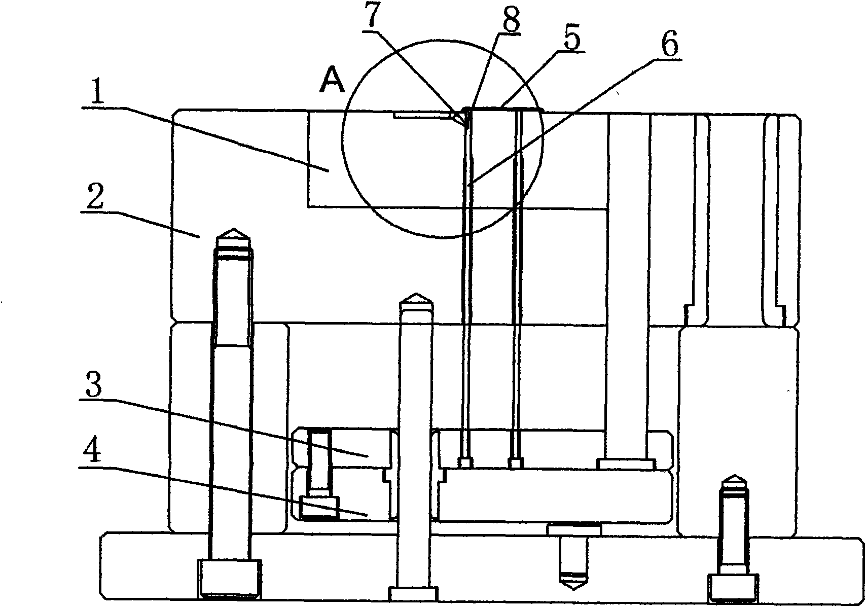
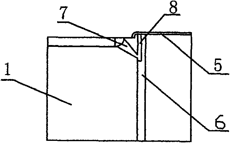
[0012] Such as Figure 1~4 As shown, the ejector gate of the injection mold includes a movable model cavity 1, a movable template 2, a push rod fixing plate 3, a push plate 4, a ejector rod 6, and a runner 7. The movable model cavity 1 is fixed on the movable template 2 by screws. On the surface of the movable model chamber 1, there is a runner 7, and the ejector rod 6 is fixed on the push rod fixing plate 3 through the push plate 4. The gap 8 communicates directly opposite.

[0013] The cavity formed by the semicircular notch 8 is the gate, and the size of the gate can be changed by modifying the size and height of the notch for different product sizes and thicknesses. In order to ensure the strength of the ejector pin 6, it is recommended that its diameter should not be less than 3mm. In order to ensure that the products with special shapes can be taken off smoothl...


PUM


Abstract

The invention relates to a carrier rod type gate for an injection mold. The gate comprises a movable mold cavity, a movable template, a push rod fixing plate, a push plate, a carrier rod and a runner, wherein the movable mold cavity is fixed on the movable template through screws; the runner is arranged on the surface of the movable mold cavity; the carrier rod is fixed on the push rod fixing plate through the push plate; a semicircular notch is formed on the top of the carrier rod; the runner is opposite to and communicated with the semicircular notch; and a rotation stopping surface is arranged at the bottom of the carrier rod. The carrier rod type gate for the injection mold has a simple structure, works stably and is convenient to process; the injection molding period is greatly shortened; and one end of the curved runner extends to the internal side surface of a plastic product (the top surface of the mold cavity), so that the external surface of the plastic product is traceless, smooth and attractive and the requirements of people are met.

Description

technical field [0001] The invention relates to an arrangement mechanism for an injection mold, which is especially suitable for plastic products whose outer surface of a thin-walled product does not allow arranging a glue runner and is difficult to feed glue from the side. The injection mold in which the glue runner is arranged inside the plastic product Pin gate. Background technique [0002] In injection molds, the ways of product injection generally include: straight gate, side gate, latent gate, flat gate and point gate, etc. For some thin-walled or small products that require high deformation accuracy, the latter two are generally selected. With the continuous increase of people's demand for various thin-walled plastic parts, especially the micro-shape and surface appearance of plastic exterior parts for mobile phones and other communication products, the traditional two-plate mold flat gate and three-plate mold point The injection method of the gate mold can no long...

Claims


Application Information

Patent Timeline
IPC IPC(8): B29C45/27
Inventor 逯赵毅闫丽丽
Owner TIANJIN ZHONGHUAN SANFENG ELECTRONICS
Learn More