
Direct pushing core drawing device

A core-pulling device and straight jacking technology, which is applied in the field of mold core-pulling, can solve problems such as the inability to use inclined jacks and the inability to force ejection of undercuts.

Inactive Publication Date: 2011-02-02
VANGUARD TECH WUXI
View PDF4 Cites 3 Cited by
  • Summary
  • Abstract
  • Description
  • Claims
  • Application Information

AI Technical Summary

Problems solved by technology

[0002] During the ejection process of some products, some undercuts cannot be forced out due to product reasons, and inclined ejectors cannot be used.

Method used


Image

  • Direct pushing core drawing device
  • Direct pushing core drawing device

Examples


Embodiment Construction

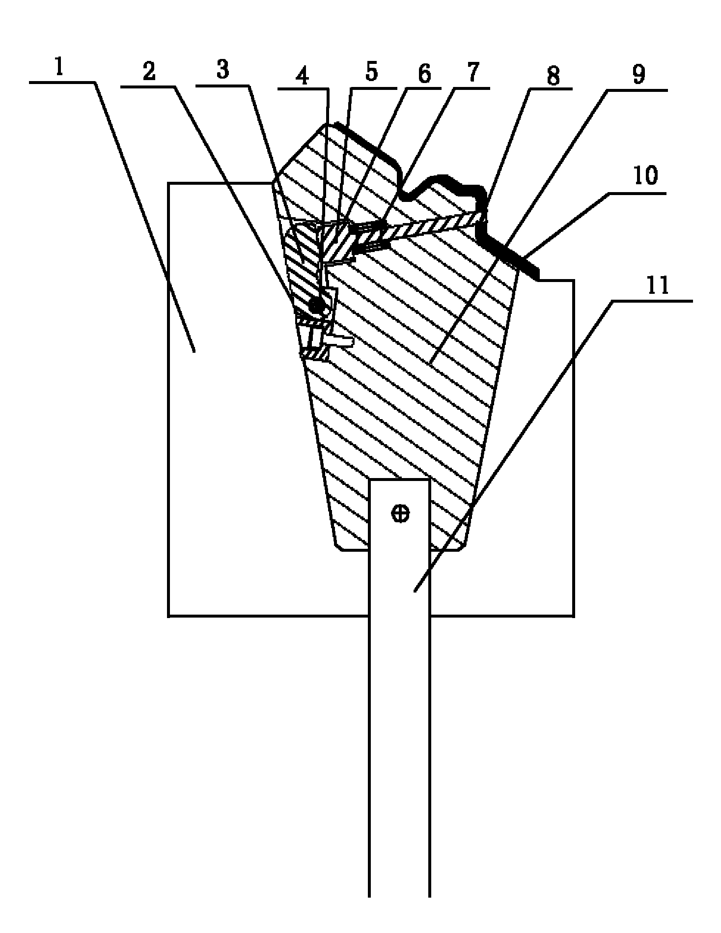
[0007] See figure 1 , a straight top core-pulling device of the present invention, including a slanted top 9, a slanted top rod 11 and a lower mold cavity 1, a T-shaped slanted thimble pin 5 is movably installed on the slanted top 8 through a slanted top sinker 6 and a spring 7, and a stopper 3 is movably connected with the slanted top 9 through the column pin 4, the stopper 3 is in contact with one end of the T-shaped slanted thimble 5, the stopper 3 compresses the spring 7 through the T-shaped slanted thimble 5, and the slanted top 9 is placed in the lower mold cavity 1, showing V-shaped contact (2 in the figure is the contact surface between the inclined top 9 and the lower mold cavity 1). The inclined thimble is pulled out to make the undercut 8 in the product 10 release. Since the stopper is placed in the lower mold cavity by relying on the spring to compress the T-shaped slanted thimble, when the mold is ejected, the slanted ejector leaves the contact surface, and the sp...


PUM


Abstract

The invention provides a direct pushing core drawing device. When an oblique pusher cannot be used, an inverted buckle of a product can be drawn out simply after the product is pushed outwards. The device comprises the oblique pusher, an oblique carrier rod and a lower die cavity and is characterized in that: a T-shaped oblique pushing needle is movably arranged on the oblique pusher through an oblique pusher settling tank and a spring; a check block is movably connected with the oblique pusher through a pin, is contacted with one end of the T-shaped oblique pushing needle and compresses the spring through the T-shaped oblique pushing needle; and the oblique pusher is arranged in and contacted with the lower die cavity in a V shape.

Description

technical field [0001] The invention relates to the technical field of mold core pulling, in particular to a straight top core pulling device. Background technique [0002] During the ejection process of some products, some undercuts cannot be forced out due to product reasons, and inclined ejectors cannot be used. Contents of the invention [0003] In view of the above problems, the present invention provides a straight top core pulling device, which can simply pull out the undercut of the product after the product is ejected when the inclined top is not used. [0004] Its technical solution is as follows: a straight top core-pulling device, which includes an inclined top, an inclined ejector rod and a lower mold cavity, and is characterized in that a T-shaped inclined top is installed on the inclined top through an inclined top sinking groove and a spring The thimble, the stopper is movably connected with the slanted top through the pin, the stopper is in contact with o...

Claims


Application Information

Patent Timeline
IPC IPC(8): B29C33/44
Inventor 张卫
Owner VANGUARD TECH WUXI
Learn More