Diode laser structure to generate diode laser radiation with optimized fiber coupling radiation parameter product

A diode laser, beam parameter product technology, used in lasers, laser devices, laser parts, etc., can solve problems such as large structural space, troublesome transmitter operation and positioning, and achieve the effect of improving input power and/or efficiency

Active Publication Date: 2011-01-19
TRUMPF LASER GMBH CO KG
View PDF2 Cites 1 Cited by
  • Summary
  • Abstract
  • Description
  • Claims
  • Application Information

AI Technical Summary

Problems solved by technology

However, the handling and positioning of the individual launchers is very cumbersome, moreover, this arrangement requires a relatively large construction space

Method used


Image

  • Diode laser structure to generate diode laser radiation with optimized fiber coupling radiation parameter product
  • Diode laser structure to generate diode laser radiation with optimized fiber coupling radiation parameter product
  • Diode laser structure to generate diode laser radiation with optimized fiber coupling radiation parameter product

Examples


Embodiment Construction

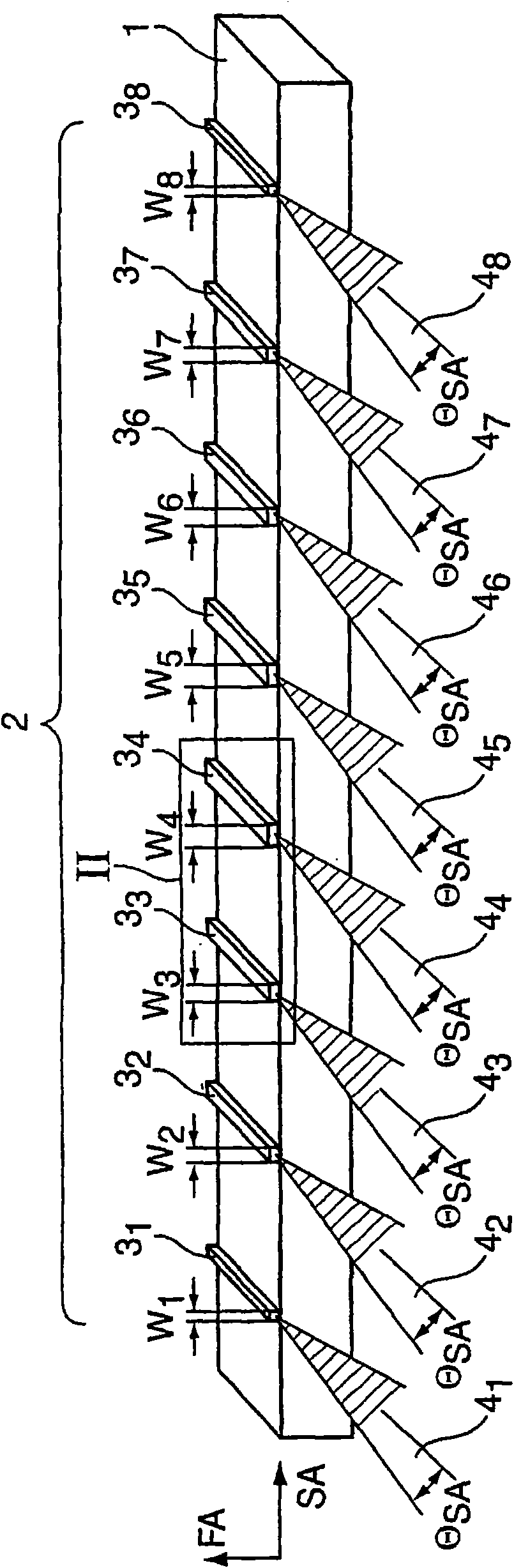
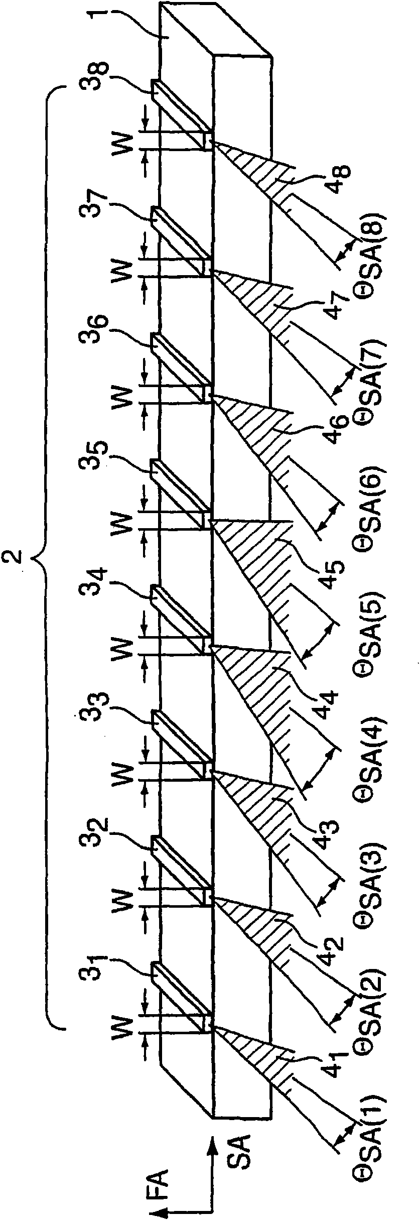
[0025] figure 1 The diode laser bar 1 shown in has a diode laser structure 2 with eight strip emitters 3 arranged in parallel next to each other 1 to 3 8 , these ribbon emitters with their SA axes in the same, at figure 1 The middle is oriented in the horizontal direction and are respectively disposed relative to each other in the horizontal direction. Ribbon Launcher 3 1 to 3 8 Several of them have different widths w in the SA direction 1 to w 8 , where the ribbon transmitter 3 1 to 3 8 The width of the diode laser structure 2 decreases, in particular mirror-symmetrically, from the center of the diode laser structure 2 towards the two edges of the diode laser structure 2 . Applicable: w 4 =w 5 >w 3 =w 6 >w 2 =w 7 >w 1 =w 8 . E.g. central launcher 3 4 、3 5 The width of is 50 to 500 μm, especially 100 to 200 μm. The emitter width decreases from one emitter to the other toward the edges by at most 50%, in particular at most 30%. The decrease in emitter width...


PUM


Abstract

In a diode laser structure (2) with a plurality of strip emitters (31 to 38) arranged side by side whose SA-axes are arranged in the same direction and at an offset to each other in this direction, wherein the beam parameter products (BPPSA) of at least a few of the strip emitters (31 to 38) are each shifted relative to the SA-axis, according to the invention the beam parameter product (BPPSA) of the strip emitters (31 to 38) decreases, starting from the middle of the diode laser structure (2), to the two edges of the diode laser structure (2), in particular in a mirror-symmetrical manner and / or from the middle of the diode laser structure (2).

Description

technical field [0001] The invention relates to a diode laser structure with a plurality of strip emitters arranged adjacent to one another, the strip emitters being aligned with their SA axes in the same direction and arranged offset relative to one another in this direction, wherein , the beam parameter products of at least several of these strip emitters differ in each case with respect to the SA axis. Background technique [0002] Such a diode laser structure is known, for example, from JP-A-06132610. [0003] In order to generate efficient and bright diode radiation, nowadays either multiple single emitters (broad-shaped emitters with a width of typically 50 to 500 μm) or multiple single-emitters / broad-broad emitters of the same width are used Diode bar (a diode bar with a fill factor of 10 to 95% consisting of typically 10 to 100 broad-band emitters of equal width). For example, diode strips with a fill factor of 30 to 50% are typically used consisting of 30 to 50 em...

Claims


Application Information

Patent Timeline
Patent Type & Authority Applications(China)
IPC IPC(8): H01S5/40G02B27/09
CPCG02B19/0004H01S5/405G02B19/0061H01S2301/18G02B19/0057H01S5/4031H01S5/4012H01S5/4081H01S5/02284H01S5/02251
Inventor S·G·P·施特罗迈尔C·蒂尔科恩
Owner TRUMPF LASER GMBH CO KG
Why Eureka
Try Eureka