Cylinder

A cylinder rod and sensor technology, applied in the field of cylinders, can solve problems such as unfavorable maintenance and high cost of cylinder manufacturing, and achieve the effects of reducing production costs and reducing leakage magnetic fields.

Active Publication Date: 2011-01-19
ZF CV SYST EURO BV
View PDF5 Cites 6 Cited by
  • Summary
  • Abstract
  • Description
  • Claims
  • Application Information

AI Technical Summary

Problems solved by technology

Likewise, the disadvantages are that the cylinders are expensive to manufacture and are not conducive to maintenance

Method used


Image

  • Cylinder
  • Cylinder
  • Cylinder

Examples


Embodiment Construction

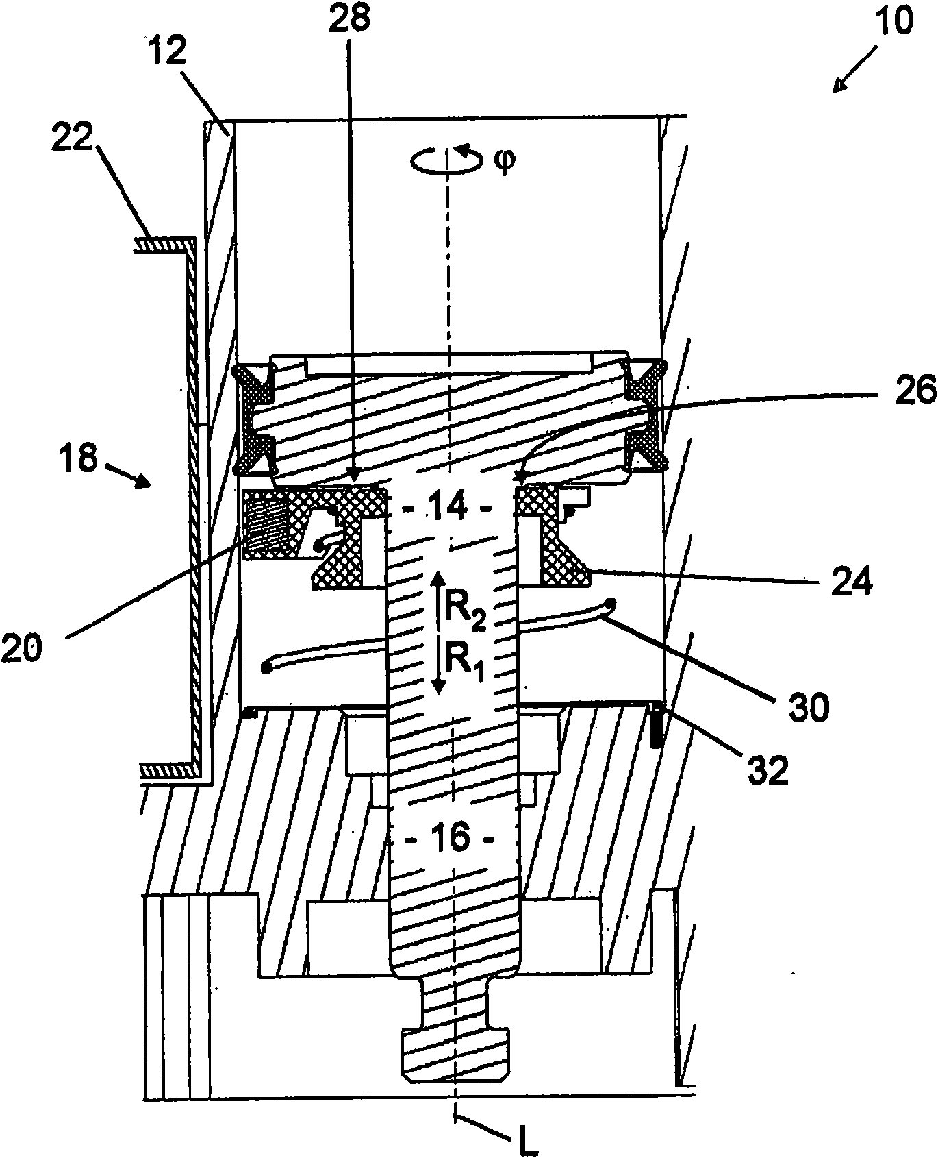
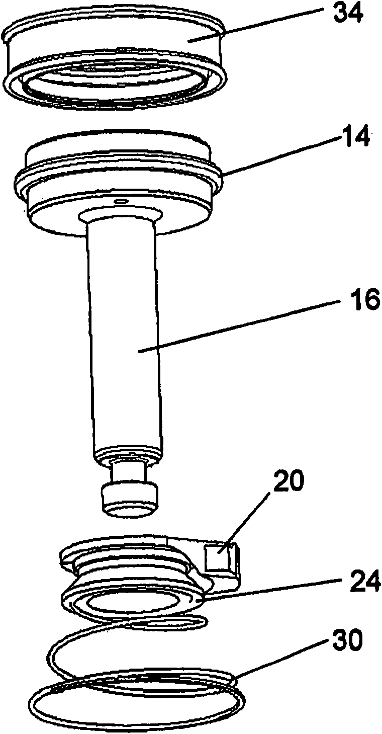
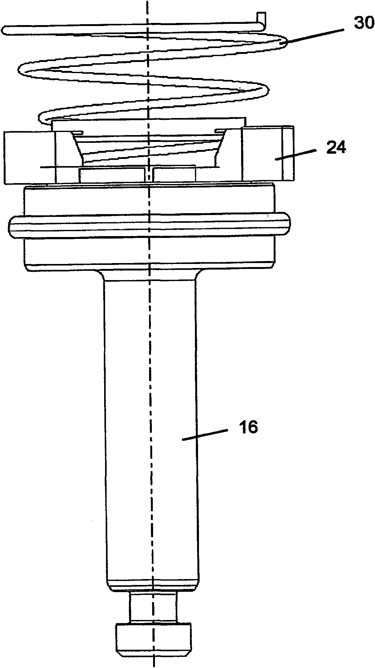
[0025] figure 1 A cylinder 10 is shown with a piston 14 running in a cylinder housing 12 , which is fastened on a cylinder rod 16 and is fixed rotatably about a cylinder rod longitudinal axis L .

[0026] Furthermore, the cylinder 10 comprises a position sensor 18 comprising a sensor magnet 20 and a sensor element 22 cooperating with the sensor magnet 20 . The position sensor 18 is designed in such a way that the position sensor 18 detects the position of the piston 14 at a height relative to the longitudinal axis L of the cylinder rod.

[0027] The piston 14 is rotatable about the longitudinal axis L through an angle of rotation with respect to the cylinder housing 12 The sensor magnet 20 is always arranged opposite the sensor element 22 with respect to the cylinder housing 12 in that the sensor magnet 20 is arranged in a rotationally fixed manner with respect to the cylinder housing 12 . Furthermore, the sensor magnet 20 is fixed on the adapter 24 . For example, the sens...


PUM


Abstract

The invention relates to a cylinder having a piston (14) moving in a cylinder housing (12), said piston being fastened to a cylinder rod (16) and rotatable about a cylinder longitudinal axis (L), and further having a position sensor (18), comprising a sensor magnet (20) and a sensor element (22), which interacts with the sensor magnet (20), and which is configured for detecting a cylinder rod position relative to the cylinder housing (12). The invention provides that the sensor magnet (20) is fastened on the cylinder rod rotatably with respect to the cylinder rod (16) and is guided non-rotatably with respect to the cylinder housing (12).

Description

technical field [0001] The invention relates to a cylinder with a piston running in a cylinder housing, the piston being fixed on a cylinder rod and rotatable about a cylinder axis, and a position sensor comprising a sensor magnet and a sensor element cooperating with the sensor magnet , wherein a sensor magnet is configured for detecting the position of the cylinder rod relative to the cylinder housing. Furthermore, adjacently arranged sensors may be disturbed by sub-magnets. Background technique [0002] Such a piston is known, for example, from DE 20 2005 005 508 U1. In this case, sub-magnets that complement the magnetic ring are arranged on the piston, the magnetic fields of which are detected by magnetic field sensors. A disadvantage of such pistons is their high production outlay. [0003] A fluid cylinder with a position detection device for the position of the piston is known from DE 20 2007 001 020 U1. Likewise, the disadvantages are that the cylinders are expen...

Claims


Application Information

Patent Timeline
Patent Type & Authority Applications(China)
IPC IPC(8): F15B15/28
CPCF15B15/1447F15B15/2815F15B15/2861
Inventor 延斯-托尔斯滕·格罗瑙米可·霍伊里希克里斯蒂安·泽斯塔特蒂诺·维格斯
Owner ZF CV SYST EURO BV
Why Eureka
Try Eureka