
Lighting glasses

A technology for glasses and eye masks, which is applied in the field of hands-free light-emitting devices, and can solve problems such as contact surface wear, flicker, and appearance deterioration

Inactive Publication Date: 2014-01-22
迈克尔·沃特斯
View PDF15 Cites 0 Cited by
  • Summary
  • Abstract
  • Description
  • Claims
  • Application Information

AI Technical Summary

Problems solved by technology

Likewise, repeated use can cause wear on the mating surfaces of the contacts, as well as flicker problems due to intermittent conduction of the contacts
Also, if the glasses are only hinged, the light is always on when the temple arms are pivoted open and therefore cannot be used as non-lit glasses in general
One solution is to provide another on-off switch, but this undesirably increases the complexity and cost of the illuminated glasses and requires additional electronics on the glasses, which results in a poorer appearance

Method used


Image

  • Lighting glasses
  • Lighting glasses
  • Lighting glasses

Examples


Embodiment Construction

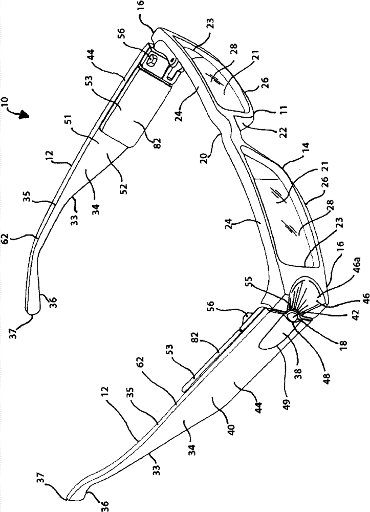
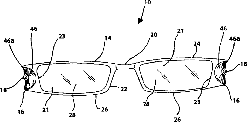
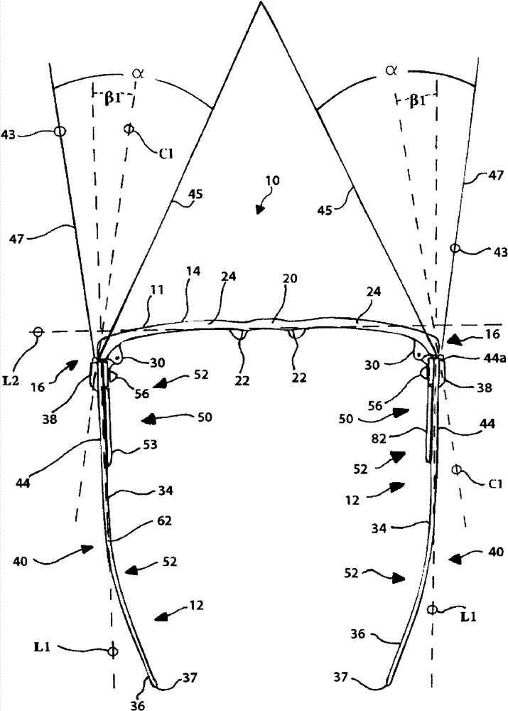
[0043] In general and as further described below, illuminated eyewear, which may or may not include a lens or lenses 21 attached thereto, is provided that provides forward lighting to the wearer. The illuminated eyewear 10 may be constructed with a conventional eyeglass frame 11 having a plurality of generally rigid frame elements including a pair of spaced apart temple arm elements 12 and a front cross brace extending transversely between the temple arm elements 12. Element 14. As shown, the temple arm member 12 is pivotally connected to the cross brace member 14 via a hinge 30 at the junction between the transversely opposite end 16 of the cross brace member 14 and the front end 44 of the temple arm member 12 .

[0044] Other configurations of the frame 11 of the light-emitting glasses 10 are also conceivable, including cross-brace elements 14 modified to include several parts or parts, or for example by only including intermediate bridges or elements 20 connected to the len...


PUM


Abstract

Illuminated eyewear is provided. In one form, the temple arm members have all the lighting components mounted thereto including for each temple arm member a light, power source for the light, and electrical connections including a switch for providing power from the power source to the light. In another form, the cross-frame member has blinder portions integrally formed at either end thereof which are configured to block stray light to avoid glare problems. The blinder portions preferably include surfaces that are inclined to generally extend along the light cone generated by an LED light source mounted to the front end portion of each of the temple arm members. In another form, the temple arm members each have a recessed cavity formed in inner surface portion thereof in which the power source and switch components are received with the switch actuator mounted to the inner surface portion so it is hidden from view when the eyewear is worn for enhanced aesthetics.

Description

technical field [0001] The present invention relates to hands-free lighting devices, and more particularly to illuminated eyewear. Background technique [0002] Often an individual needs a light source to illuminate an area while performing a task or needs a light source pointing in a generally outward direction for visibility. One option is to carry a flashlight, but such lighting devices are often cumbersome and often interfere with task completion by having to hold the flashlight. For this reason, hands-free lighting fixtures are often employed because the illumination required by the individual does not require a fixed light source. Common types of hands-free lighting include light sources mounted on helmets or glasses. [0003] Light sources on eyeglasses typically include a light source (which may be an LED) mounting structure on the crosspiece or temple of the eyewear to provide forward illumination to the wearer. In such configurations, light-emitting glasses are ...

Claims


Application Information

Patent Timeline
Patent Type & Authority Patents(China)
IPC IPC(8): G02C11/04G02C5/14G02C5/02F21V33/00F21V23/06F21V23/04F21Y101/02
CPCG02C11/04G02C5/146F21V33/00G02C3/00
Inventor 迈克尔·沃特斯
Owner 迈克尔·沃特斯
Learn More