Key-press input module
A technology of input modules and buttons, applied in simulators, instruments, computer control, etc., can solve problems such as easy burning, complicated circuits, and inconvenience for drivers and pedestrians
- Summary
- Abstract
- Description
- Claims
- Application Information
AI Technical Summary
Problems solved by technology
Method used
Image
Examples
Embodiment 1
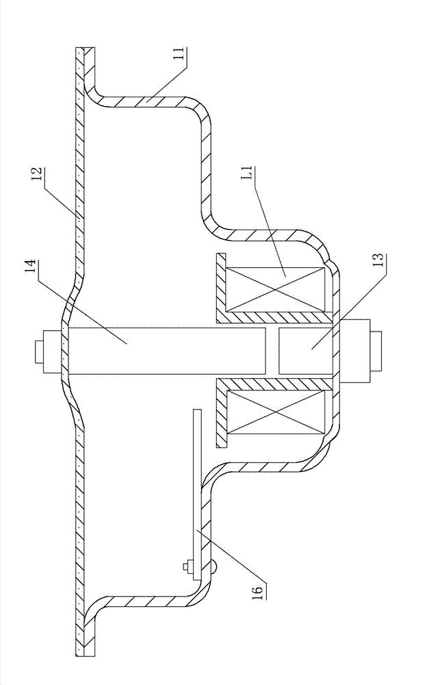
[0054] Embodiment 1: See Figure 1, Figure 5 , in the figure, the electric horn intelligent control device includes a bowl-shaped bottom shell 11, a static iron core 13, a moving iron core 14, a coil L1, a vibrating membrane 12, and a control circuit. The vibrating membrane 12 covers the top of the bowl-shaped bottom shell 11. The iron core 13 is fixed in the middle of the bowl-shaped bottom shell 11, and a moving iron core 14 is arranged above the static iron core 13. The moving iron core 14 is fixedly connected with the middle part of the vibrating membrane 12, and the coil L1 is set on the static iron core 13 and Outside the moving iron core 14, the circuit board 16 containing the control circuit is fixed on the inner wall of the bowl-shaped bottom shell 11. The control circuit contains a micro-processing module 1, a power supply module 2, a coil drive module 3, a key input module 4, and a vibrating membrane vibration The signal detection module 5, the microprocessing modul...
Embodiment 2
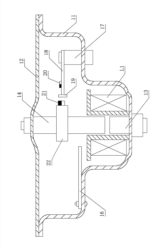
[0079] Embodiment 2: Referring to Fig. 2 and Fig. 6, the numbers in the figures are the same as those in Embodiment 1, the meanings of representation are the same, and the working process is basically the same. The module 5 includes a linear Hall sensor 19, the output end of the linear Hall sensor 19 is connected to the analog signal input end AN2 of the single-chip microcomputer U1, the source electrode of the field effect transistor V2 is grounded, and the inner wall of the bowl-shaped bottom case 11 is vertically fixed with a pillar 17 , a bracket 18 is fixed laterally on the pillar 17, and one end of the bracket 18 is installed with a linear Hall sensor 19 and the linear Hall sensor 19 is close to the moving iron core 14. The outer surface of the moving iron core 14 is provided with a fixed card 22, on the fixed card 22 A permanent magnet 21 corresponding to the position of the linear Hall sensor 19 is installed, the sensing area of the linear Hall sensor 19 is arranged b...
Embodiment 3
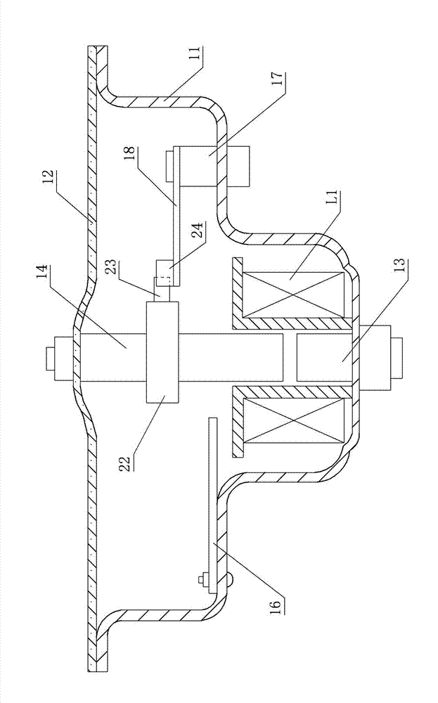
[0082] Embodiment 3: see Figure 3, Figure 7 , the number in the figure is the same as that of the first embodiment, the meaning is the same, and its working process is basically the same, and the similarities will not be repeated. The photocoupler 24 contains an emitting diode L2 and a linear illuminance sensor U4. The anode of the emitting diode L2 is connected to the power supply terminal of the single-chip microcomputer U1 through the resistor R10, and the + terminal of the linear illuminance sensor U4 is connected to the power supply terminal of the single-chip microcomputer U1 through the resistor R11. The + terminal of U4 is also connected to the analog signal input terminal AN2 of the single-chip microcomputer U1. A pillar 17 is vertically fixed on the inner wall of the bowl-shaped bottom case 11, and a bracket 18 is horizontally fixed on the pillar 17. One end of the bracket 18 is installed with a linear photocoupler 24 And the linear photocoupler 24 is close to the m...
PUM
 Abstract
Description
Claims
Application Information
 - R&D
- Intellectual Property
- Life Sciences
- Materials
- Tech Scout
- Unparalleled Data Quality
- Higher Quality Content
- 60% Fewer Hallucinations
Browse by: Latest US Patents, China's latest patents, Technical Efficacy Thesaurus, Application Domain, Technology Topic, Popular Technical Reports.
© 2025 PatSnap. All rights reserved.Legal|Privacy policy|Modern Slavery Act Transparency Statement|Sitemap|About US| Contact US: help@patsnap.com


